Kernel fault injection method and electronic device
A technology for fault injection and electronic equipment, applied in the computer field, can solve the problems of prolonged application development cycle and long waiting time for fault injection, and achieve the effect of reducing waiting time, shortening development cycle, and reducing the number of instructions
- Summary
- Abstract
- Description
- Claims
- Application Information
AI Technical Summary
Problems solved by technology
Method used
Image
Examples
Embodiment 1
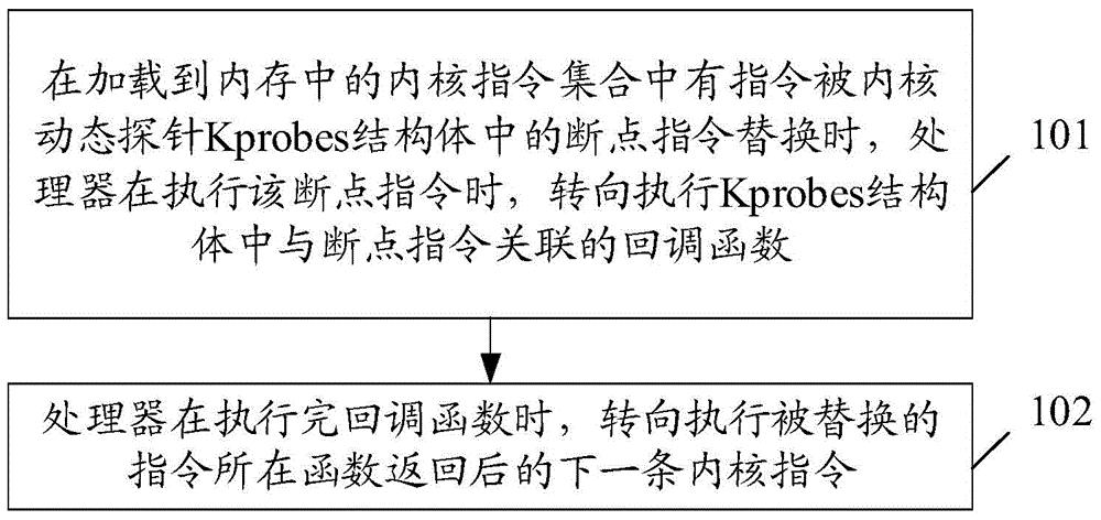
[0063] see figure 2 , is a schematic flow diagram of the kernel fault injection method provided in the embodiment of the present application, the flow includes:
[0064] Step 101: When an instruction in the kernel instruction set loaded into the memory is replaced by a breakpoint instruction in the Kprobes structure of the kernel dynamic probe, when the processor executes the breakpoint instruction, it turns to execute the breakpoint in the Kprobes structure The callback function associated with the instruction;
[0065] Step 102: After the processor finishes executing the callback function, it turns to execute the next kernel instruction after the function of the replaced instruction returns.
[0066] For ease of understanding, first introduce the setting of the detection point, that is, the process of replacing the detected kernel instruction with a breakpoint instruction, which is implemented in the registration process of the Kprobes structure. It should be noted that t...
Embodiment 2
[0105] In view of the technical problem in the prior art that there is a lack of injection methods for delay-type faults when kernel functions are called, Embodiment 2 of the present application provides a kernel fault injection method, see Figure 5 , the method includes the following:
[0106] Step 401: When an instruction in the kernel instruction set loaded into the memory is replaced by a breakpoint instruction in the Kprobes structure, when the processor executes the breakpoint instruction, it turns to execute the Kprobes structure associated with the breakpoint instruction The callback function generates a time delay of a set duration, where the set duration is the time parameter included in the callback function;
[0107] Step 402: The processor executes the replaced instruction after generating the set time delay.
[0108] Specifically, in step 401, in the kernel instruction set loaded into the memory, some instructions are replaced by breakpoint instructions when th...
Embodiment approach
[0113] First, when executing the callback function, first record the first time when the processor starts to execute the callback function; after recording the first time, record the time at that time again, and judge whether the time difference between this time and the first time reaches the setting If the duration is reached, it is determined that the time is the second time; otherwise, the above steps are repeated until the second time is determined. Wherein, the operation of recording the current time can be realized by calling the dogettimeofday function.
[0114] Second, when the callback function is executed, a timer will be started, and when the timer reaches the set time, the callback function will be executed. Wherein, the time difference between the set time and the time of starting the timer is the aforementioned set duration.
[0115] Through the above two methods, the purpose of manufacturing the set time delay can be realized quickly and accurately, and it is ...
PUM
 Abstract
Description
Claims
Application Information
 - R&D
- Intellectual Property
- Life Sciences
- Materials
- Tech Scout
- Unparalleled Data Quality
- Higher Quality Content
- 60% Fewer Hallucinations
Browse by: Latest US Patents, China's latest patents, Technical Efficacy Thesaurus, Application Domain, Technology Topic, Popular Technical Reports.
© 2025 PatSnap. All rights reserved.Legal|Privacy policy|Modern Slavery Act Transparency Statement|Sitemap|About US| Contact US: help@patsnap.com


