Fingerprint recognition device and manufacturing method thereof

A technology for fingerprint identification and manufacturing method, which is applied in the directions of acquiring/organizing fingerprints/palmprints, character and pattern recognition, and printing image acquisition, etc., which can solve the problem that the fingerprint reader cannot effectively perform fingerprint identification, reduce the sensitivity of fingerprint identification, and reduce the level difference. And other issues

Active Publication Date: 2017-07-07
TPK TOUCH SOLUTIONS (XIAMEN) INC
View PDF4 Cites 1 Cited by
  • Summary
  • Abstract
  • Description
  • Claims
  • Application Information

AI Technical Summary

Problems solved by technology

However, since both the light-shielding layer and the pattern layer are coated on the inner surface of the cover plate by printing, although theoretically the raw material of the pattern layer can only be coated on the exposed parts of the light-shielding layer, in practice, printing tolerances will vary. A small amount of pattern layer material is covered on the light-shielding layer, causing the lower surface of the pattern layer to be farther away from the cover plate than the lower surface of the light-shielding layer, resulting in a step difference
Such a step difference will increase the distance from the top surface of the fingerprint reader to the outer surface of the cover, reduce the sensitivity of fingerprint recognition, and even cause the fingerprint reader to be unable to effectively perform fingerprint recognition.

Method used


Image

  • Fingerprint recognition device and manufacturing method thereof
  • Fingerprint recognition device and manufacturing method thereof
  • Fingerprint recognition device and manufacturing method thereof

Examples


Embodiment Construction

[0058] A number of embodiments of the present invention will be disclosed in the following figures. For the sake of clarity, many practical details will be described together in the following description. However, those skilled in the art should understand that in some embodiments of the present invention, these practical details are not necessary, and thus should not be used to limit the present invention. In addition, for the sake of simplifying the drawings, some well-known structures and components will be shown in a simple and schematic manner in the drawings. In addition, for the convenience of readers, the size of each element in the drawings is not drawn according to actual scale.

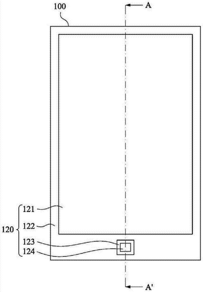
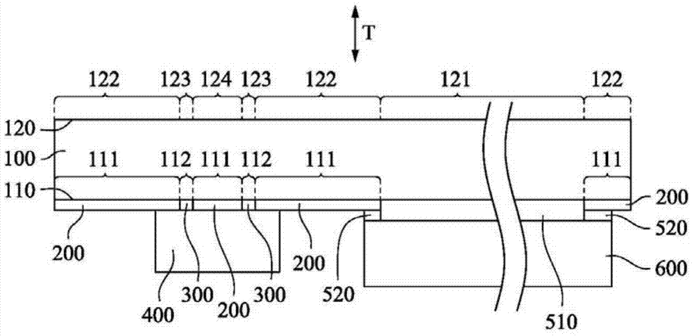
[0059] figure 1 A schematic top view of a touch device according to an embodiment of the present invention is shown. figure 2 draw figure 1 The cross-sectional view of the touch device shown along line A-A'. Such as figure 1 and 2 As shown, in this embodiment, the touch device includ...


PUM


Abstract

The invention provides a fingerprint recognition device and a manufacturing method thereof, which include a light-transmitting cover plate, a first light-shielding layer, a pattern layer and a fingerprint recognizer. The transparent cover has an inner surface. The inner surface has a first area and a second area. The first area is adjacent to the second area. The first light-shielding layer is arranged on the first area of ​​the inner surface. The first light-shielding layer has a first bottom surface opposite to the inner surface. The pattern layer is disposed on the second area of ​​the inner surface. The color of the pattern layer is different from that of the first light-shielding layer. The pattern layer has a second bottom surface opposite to one of the inner surfaces. The maximum step difference between the first bottom surface and the second bottom surface is less than or equal to 6 microns. At least part of the first light-shielding layer and the pattern layer are located between the fingerprint reader and the transparent cover. In this way, the influence of the light-shielding layer and the pattern layer on the sensitivity of the fingerprint reader is reduced, and the fingerprint recognition sensitivity is improved.

Description

technical field [0001] The invention relates to an electronic device, and in particular to a fingerprint recognition device and a manufacturing method thereof. Background technique [0002] Since the fingerprint identification technology can play a good role in anti-theft and personal privacy protection, it has been gradually applied to mobile devices in recent years to prevent the mobile device from being stolen. Specifically, such mobile devices include covers, fingerprint readers, and touch display devices. The touch display device is arranged in the central area of ​​the inner surface of the cover for user operation and information display. The fingerprint recognizer is arranged on the peripheral area of ​​the inner surface of the cover to identify the user's fingerprint. [0003] In order to shield the peripheral wires of the touch display device, a light-shielding layer is provided on the peripheral area of ​​the inner surface of the cover plate. In addition, in ord...

Claims


Application Information

Patent Timeline
Patent Type & Authority Patents(China)
IPC IPC(8): G06K9/00
CPCG06V40/1318
Inventor 李裕文许良珍杨河波蔡辉虎苏富榆张羽
Owner TPK TOUCH SOLUTIONS (XIAMEN) INC
Why Eureka
Try Eureka