A mhl cable and a virtual reality device
A cable and signal line technology, applied in the field of virtual reality equipment, can solve the problems of MHL cable EMI interference, EMI can not be suppressed, etc., to achieve the effect of reducing electromagnetic interference, reducing electromagnetic radiation interference, and enhancing effectiveness
- Summary
- Abstract
- Description
- Claims
- Application Information
AI Technical Summary
Problems solved by technology
Method used
Image
Examples
Embodiment 1
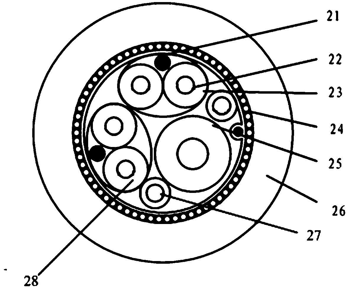
[0027] figure 1 It is a schematic diagram of the structure of the MHL cable before improvement, figure 2 is a cross-sectional schematic diagram of the MHL cable before improvement; figure 1 and figure 2 , the signal transmission line of the existing virtual reality equipment needs a power supply and a video source respectively, so it often adopts a split structure, that is, an MHL cable is drawn from the interface P3 of the main board, and two cables are respectively connected to the end of the cable. There are two ports P1 and P2, where port P1 is connected to the power supply, and port P2 is connected to the video source.
[0028] see figure 2 , 21 represents the MHL signal ground wire, 22 represents the MHL+ / - differential signal wire, 23 represents the shielding layer, 24 represents the shielding layer, 25 represents the power control line VBUS, 26 represents the insulation layer, 27 represents the ground wire, 28 represents the D+ / of USB - The differential signal ...
Embodiment 2
[0034] Figure 4 It is a structural schematic diagram of an MHL cable according to another embodiment of the present invention. This embodiment mainly describes the overall structure of the MHL cable and the connection of the pins. For other content, refer to other embodiments of the present invention, which will not be repeated here. The following combination Figure 4 The structure of the MHL cable in this embodiment will be specifically described.
[0035] see Figure 4 The MHL cable provided by the present invention also includes three interfaces, wherein the first interface P1 is a power interface (such as a USB interface), the second interface P2 is an MHL interface, and the third interface P3 is a motherboard interface, which can be connected to On the motherboard of head-mounted display devices such as virtual reality devices. Depend on Figure 4 It can be seen in the figure that the power interface P1 includes four pins, which are power pins, a pair of USB differ...
Embodiment 3
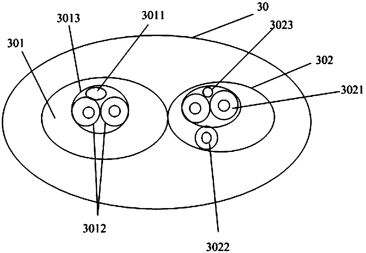
[0041] Figure 5 is a schematic cross-sectional structure diagram of an MHL cable according to another embodiment of the present invention, Figure 6 It is a schematic diagram of the cross-sectional structure of the MHL signal line group of the MHL cable according to another embodiment of the present invention, Figure 7 It is a schematic diagram of the cross-sectional structure of the USB signal line group of the MHL cable according to another embodiment of the present invention. This embodiment mainly describes the wire groups included in the MHL cable. For other content, refer to other embodiments of the present invention, which will not be repeated here. The following combination Figure 5 to Figure 7 , the connection structure of the internal signal line groups of the MHL cable in this embodiment will be described in detail.
[0042] see Figure 5 , the MHL cable in this embodiment includes an MHL signal line set 501 and a USB signal line set 502 .
[0043] combine ...
PUM
 Abstract
Description
Claims
Application Information
 - R&D
- Intellectual Property
- Life Sciences
- Materials
- Tech Scout
- Unparalleled Data Quality
- Higher Quality Content
- 60% Fewer Hallucinations
Browse by: Latest US Patents, China's latest patents, Technical Efficacy Thesaurus, Application Domain, Technology Topic, Popular Technical Reports.
© 2025 PatSnap. All rights reserved.Legal|Privacy policy|Modern Slavery Act Transparency Statement|Sitemap|About US| Contact US: help@patsnap.com


