Transmission system and base station antenna therefor
A transmission system and transmission shaft technology, applied in the direction of antennas, electrical components, etc., can solve the problems of not being able to protect the RCU module well, complex connections of various modules of the transmission system, and increasing the external space occupied by the antenna, so as to reduce cable assembly and protection Problems, simplicity of structure, effect of avoiding space
- Summary
- Abstract
- Description
- Claims
- Application Information
AI Technical Summary
Problems solved by technology
Method used
Image

Examples
Embodiment Construction
[0021] The present invention will be described in detail below in conjunction with the accompanying drawings and embodiments.
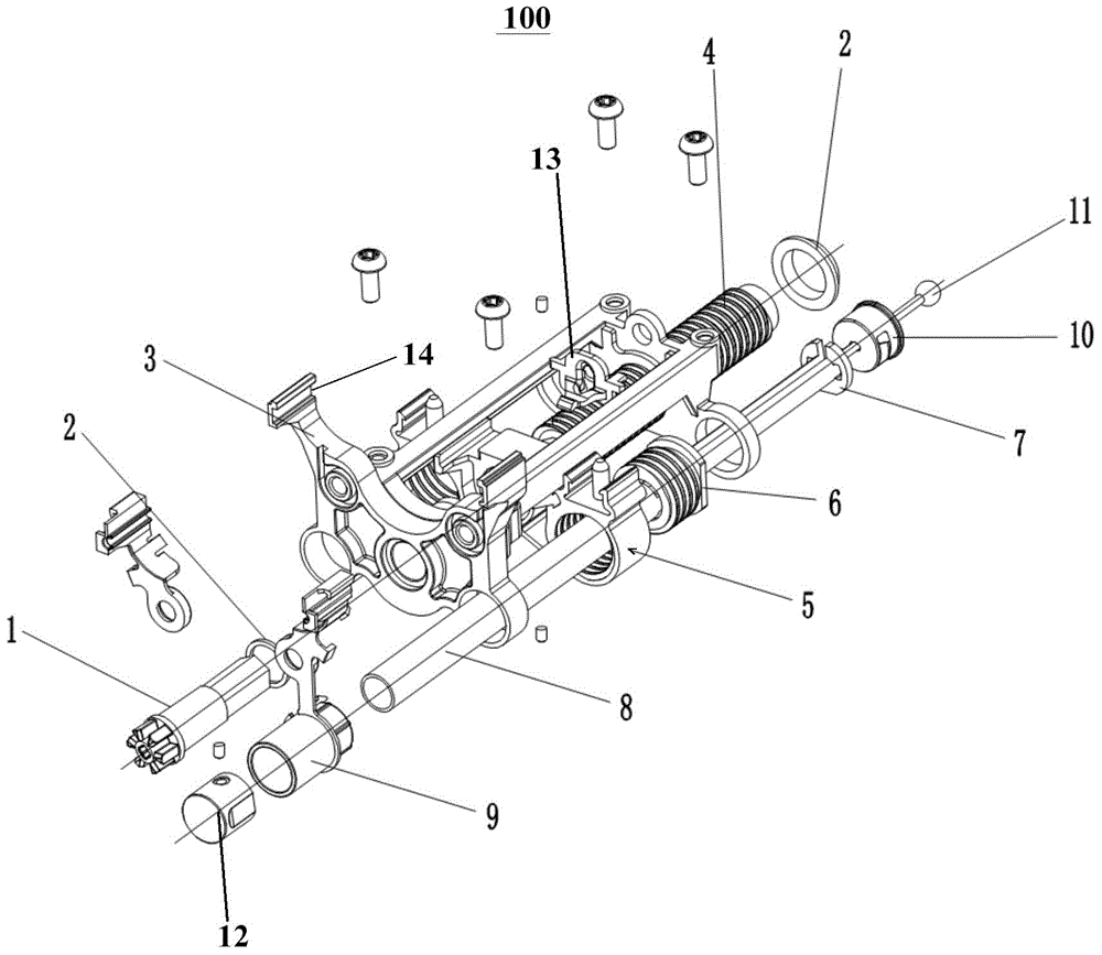
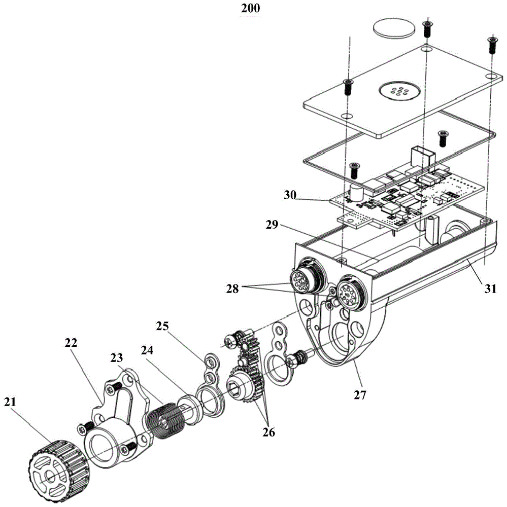
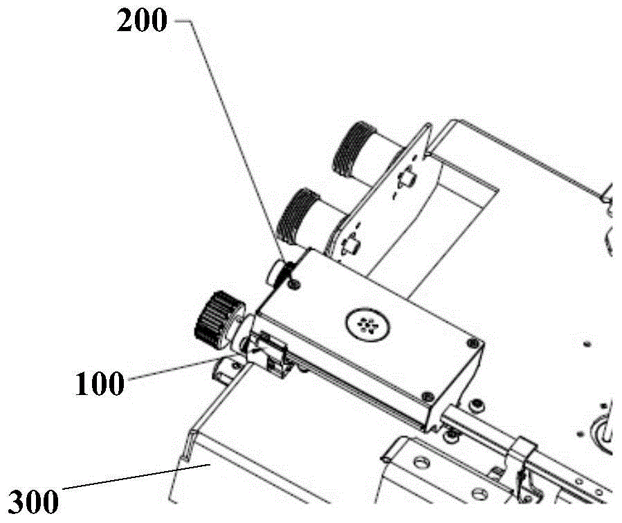
[0022] combine Figure 1-Figure 3 For reference, the present invention provides an embodiment of a transmission system, which includes: an RCU module 200 and a transmission module 100 .
[0023] Wherein, the RCU module 200 includes an RCU housing 27, a driving mechanism assembled in the RCU housing 27, and a first guiding mechanism 31 arranged on the RCU housing 27, and the output end of the driving mechanism is provided with a first transmission interface. The transmission module 100 includes a mounting frame 3, a transmission mechanism assembled on the mounting frame 3 and used to adjust the downtilt of the phase shifter, and a second guide mechanism 14 arranged on the mounting frame 3. The input end of the transmission mechanism is provided with The second transmission interface. During installation, by inserting the first guide mechanism 31 into...
PUM
 Abstract
Description
Claims
Application Information
 - R&D
- Intellectual Property
- Life Sciences
- Materials
- Tech Scout
- Unparalleled Data Quality
- Higher Quality Content
- 60% Fewer Hallucinations
Browse by: Latest US Patents, China's latest patents, Technical Efficacy Thesaurus, Application Domain, Technology Topic, Popular Technical Reports.
© 2025 PatSnap. All rights reserved.Legal|Privacy policy|Modern Slavery Act Transparency Statement|Sitemap|About US| Contact US: help@patsnap.com