Automatic sheet arranging device for grooved type commutator

A commutator and automatic row technology, applied in the commutator field, can solve the problems of increasing difficulty, large deformation of the plastic sleeve, and difficulty in inserting the copper sheet of the commutator into the plastic sleeve, etc., and achieves the effect of improving production efficiency and simple structure.

Active Publication Date: 2016-04-27
NINGBO SHENGKE COMMUTATOR
View PDF6 Cites 1 Cited by
  • Summary
  • Abstract
  • Description
  • Claims
  • Application Information

AI Technical Summary

Problems solved by technology

At present, slot-type commutators are basically used in some large-scale motors and higher-speed motors, and slot-type commutators also increase the corresponding difficulty in manually arranging chips because of their special L-shaped structure.
Because the structure of the commutator is based on copper-shaped body parts, and the copper-shaped body parts are arranged in an orderly cylindrical shape in the structure, with a directional distinction between up and down and an insulating relationship between the copper body and the copper body. In the assembly, the scattered copper-shaped parts must be gradually arranged into a cylindrical shape with the support of the plastic sleeve. During the arrangement process, the operator must be required to select the correct direction for the copper-shaped parts. Due to the large deformation of the plastic sleeve , when manually arranging, the last few commutator copper pieces are difficult to insert into the plastic sleeve

Method used


Image

  • Automatic sheet arranging device for grooved type commutator
  • Automatic sheet arranging device for grooved type commutator
  • Automatic sheet arranging device for grooved type commutator

Examples


Embodiment

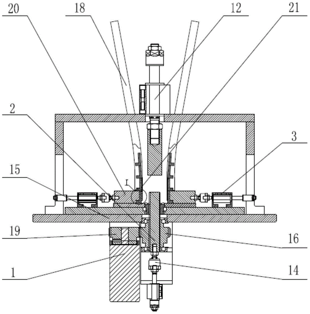
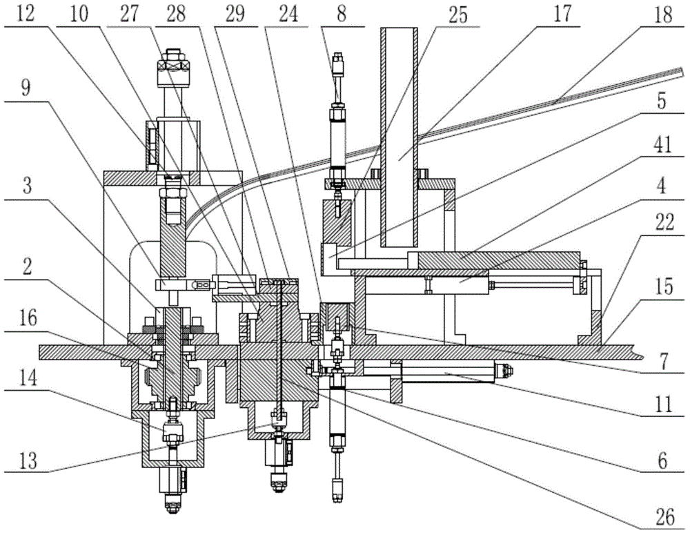
[0031] Two copper plate vibrating plates and one plastic shell vibrating plate are automatically fed to the feed guide rail 18 and the sleeve rod 17 respectively, the servo motor 1 drives the mold core 2 to rotate, and the push piece cylinder 3 drives the commutator copper plate 21 to push in respectively. Core 2. Plastic sleeve push cylinder 4 sends plastic sleeve to fixed sleeve block 5, fixed plastic sleeve cylinder 6 drives plastic sleeve mandrel 7 up, plastic sleeve delivery cylinder 8 goes down, presses plastic sleeve into plastic sleeve mandrel 7, and jacket finger 9 clamps The plastic sleeve, the rotary cylinder 10 drives the jacket finger 9 to rotate, the slider cylinder 11 drives the rotary cylinder 10, and the jacket finger 9 moves forward to the bottom of the compression sleeve cylinder 12 and waits for the sheet arranging process. After the sheet arranging process is completed, the compression plastic sleeve cylinder 12 is pressed down into the plastic sleeve, the...


PUM


Abstract

The invention relates to an automatic sheet arranging device for a grooved type commutator. The automatic sheet arranging device comprises a servo motor, a plastic sleeve push cylinder and a mounting plate. The servo motor is fixedly arranged below the front end of the mounting plate. A mold core and the center line of a plastic sleeve press cylinder arranged above the mold core superpose. Sheet pushing cylinders are arranged on two sides of the mold core in a symmetrical manner. The plastic sleeve push cylinder is disposed on the lower end surface of the inner side of a support that is positioned above the back end of the mounting plate. A push sleeve rod that slides and is connected to the extending end of the plastic sleeve push cylinder is disposed above the support. The push sleeve rod horizontally faces a fixed sleeve block arranged on one side of the support. An entry sleeve rod is vertically disposed above the push sleeve rod. A plastic sleeve feeding cylinder is vertically disposed above the fixed sleeve block. A plastic sleeve fixing cylinder is disposed below the fixed sleeve block. A slide block cylinder is horizontally disposed on one side of the plastic sleeve fixing cylinder and below the mounting plate in a transverse manner. The extending end of the slide block cylinder is connected to a rotary cylinder. The automatic sheet arranging device is simple in structure, can automatically arrange sheets, replaces conventional manual operations performed by workers, and greatly improves the production efficiency.

Description

technical field [0001] The invention relates to the field of commutators, in particular to an automatic sheet arranging device for a slot-type commutator. Background technique [0002] The commutator, commonly known as the commutator, is a part of the DC permanent magnet series motor in order to allow the motor to continue to rotate. At present, slot-type commutators are basically used in some large motors and higher-speed motors, and slot-type commutators also increase the corresponding difficulty in manually arranging chips because of their special L-shaped structure. Because the structure of the commutator is based on copper-shaped body parts, and the copper-shaped body parts are arranged in an orderly cylindrical shape in the structure, with a directional distinction between up and down and an insulating relationship between the copper body and the copper body. In the assembly, the scattered copper-shaped parts must be gradually arranged into a cylindrical shape with th...

Claims


Application Information

Patent Timeline
IPC IPC(8): H01R43/06
Inventor 王立明孙瑞良潘荣政王耀定李国法
Owner NINGBO SHENGKE COMMUTATOR
Why Eureka
Try Eureka