

Storage battery charging circuit and warehouse-in auxiliary machine test device
A charging circuit and testing device technology, which is applied to battery circuit devices, circuit devices, measuring devices, etc., can solve the problem of high cost and achieve the effect of avoiding high cost
- Summary
- Abstract
- Description
- Claims
- Application Information
AI Technical Summary
Problems solved by technology
Method used
Image

Examples
Embodiment Construction
[0030] In order to make the above objects, features and advantages of the present invention more comprehensible, specific implementations of the present invention will be described in detail below in conjunction with the accompanying drawings.
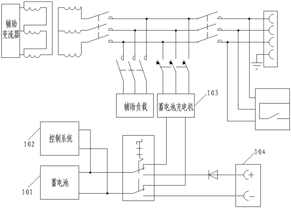
[0031] The invention provides a storage battery charging circuit to solve the problem of high cost in the prior art.
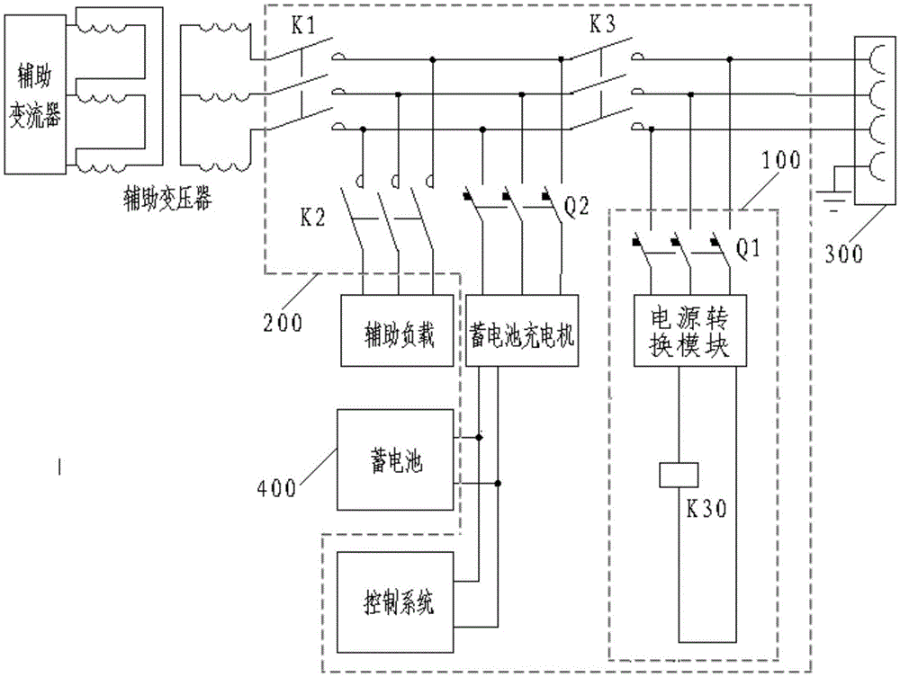
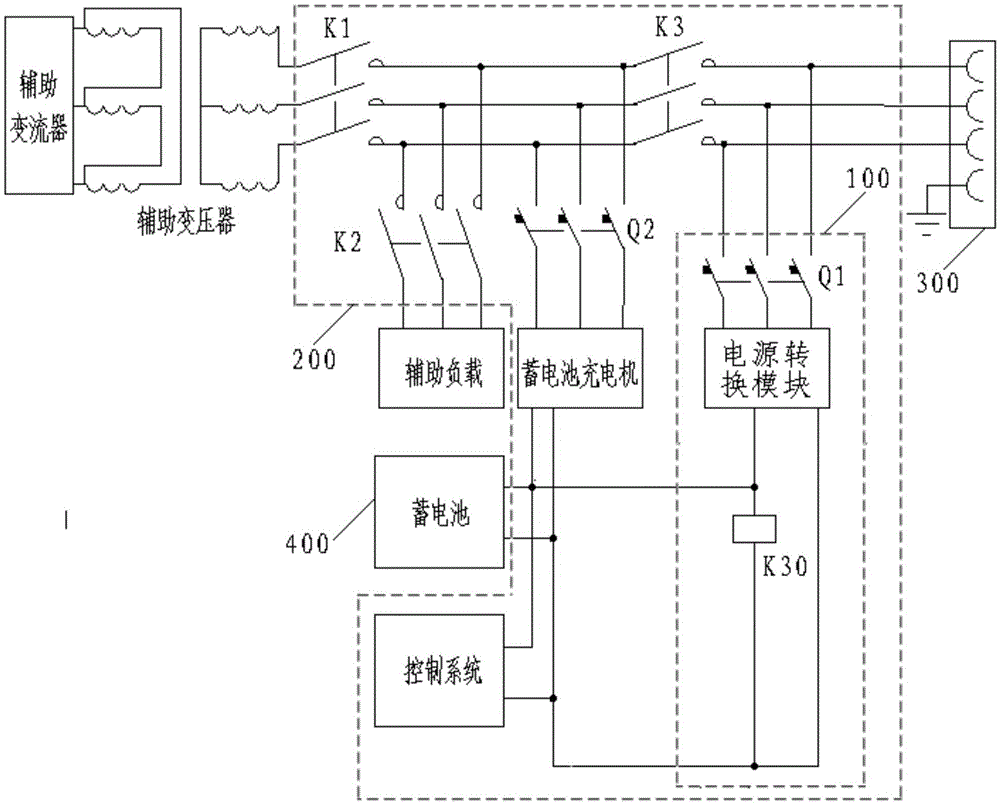
[0032] Specifically, such as figure 2 As shown, the storage battery charging circuit 100 is applied to the auxiliary machine test device 200 of the main line electric locomotive, and is connected with the main contactor of the socket 300 in the warehouse and the auxiliary machine test device 200 in the warehouse. The battery charging circuit 100 includes: a first circuit breaker Q1 and power conversion unit; where:
[0033] The input end of the first circuit breaker Q1 is connected to the socket 300 in the library, and the output end is connected to the input end of the power conversion module;
[0034] The two outp...
PUM
 Abstract
Description
Claims
Application Information