Method for determining constant voltage compensation network topology of wireless power transmission system

A wireless power transmission and compensation network technology, applied in the direction of electrical components, circuit devices, etc., can solve the problem that the parameters of the transformer are difficult to meet the requirements of constant voltage or constant current, and the design is complicated

Active Publication Date: 2016-04-27
SOUTHEAST UNIV
View PDF3 Cites 13 Cited by
  • Summary
  • Abstract
  • Description
  • Claims
  • Application Information

AI Technical Summary

Problems solved by technology

However, the output constant voltage and constant current of the above structure are affected by the parameters of the non-contact transformer. The parameters of the non-contact transformer are limited by space and distance, and the design is complicated. Under the limited space and distance, the transformer parameters may be difficult to meet. Constant voltage or constant current requirements

Method used


Image

  • Method for determining constant voltage compensation network topology of wireless power transmission system
  • Method for determining constant voltage compensation network topology of wireless power transmission system
  • Method for determining constant voltage compensation network topology of wireless power transmission system

Examples


Embodiment Construction

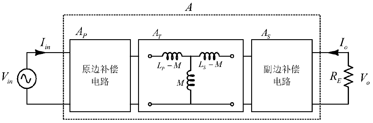
[0053] Based on the two-port network theory, the present invention determines the impedance characteristics of the entire system two-port network according to requirements such as load independence and zero phase difference of input impedance, and decomposes the system two-port network into a primary side compensation network, a non-contact transformer, and a secondary side compensation network The three sub-two-port networks are cascaded, and then the parameter characteristics of the primary and secondary resonance compensation networks are obtained. The technical solution of the invention will be described in detail below in conjunction with the accompanying drawings.

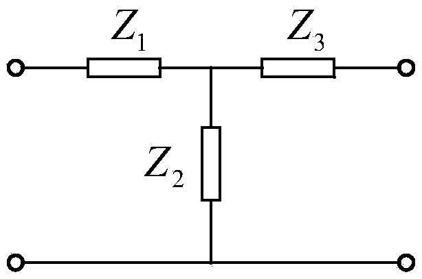
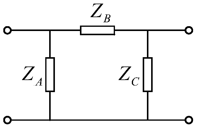
[0054] figure 1It is a block diagram of the constant voltage resonance compensation network of the present invention, including a primary side compensation circuit, a non-contact transformer, and a secondary side compensation circuit, where ω is the operating angular frequency, and C P is the capacitance val...


PUM


Abstract

The invention relates to a method for determining the constant voltage compensation network topology of a wireless power transmission system. According to the compensation network, the output voltage of the wireless power transmission system is not affected by load, and not limited by a non-contact transformer parameter, and thereby the design of the non-contact transformer can be simplified. According to the method, the compensation circuit parameter is determined with the aim that the voltage gain of the system is not affected by the system, the input impedance of the system is pure resistive, and the system efficiency is maximal, then the constant voltage compensation network topology is determined, and the constant voltage compensation network topology of which four groups of primary and secondary resonant networks can all be equivalent to T-type or n-type networks. The output voltage of the IPT system is not limited by the parameter of the non-contact transformer, and the design of the non-contact transformer is simplified; and the constant voltage output and unit power factor which are not affected by the load can be achieved at the same time, the reactive power is reduced, the requirement on device stress is lowered, and the transmission efficiency is improved.

Description

technical field [0001] The invention discloses a method for determining the topology of a constant voltage compensation network of a wireless power transmission system, which is suitable for wireless charging occasions and belongs to the technical field of wireless power transmission. Background technique [0002] Inductive Power Transfer (IPT) technology uses an alternating electromagnetic field as a medium to transmit energy to a load. Since there is no direct electrical contact, it can avoid electric sparks, is not affected by the environment, and can work in harsh environments. At present, IPT technology has been widely used in consumer electronics, lighting, electric vehicles and other fields. [0003] In order to transmit active energy efficiently, the IPT converter needs to have the following characteristics: 1. Zero reactive power, 2. Soft switching of switching devices, 3. Directly output the voltage or current required by the load. There is no reactive energy in ...

Claims


Application Information

Patent Timeline
Patent Type & Authority Applications(China)
IPC IPC(8): H02J50/10
Inventor 曲小慧景妍妍韩洪豆黄少聪谢智刚
Owner SOUTHEAST UNIV
Why Eureka
Try Eureka