Mini infrared photoelectric intravenous drip alarm device capable of displaying intravenous drip speed

An infrared light and alarm technology, applied in the field of medical assistance, can solve the problems that the infusion monitoring technology is not suitable for popularization and application, and achieve the effects of reducing mental burden, reducing work intensity and small size

Inactive Publication Date: 2016-05-04
HARBIN INST OF TECH
View PDF5 Cites 1 Cited by
  • Summary
  • Abstract
  • Description
  • Claims
  • Application Information

AI Technical Summary

Problems solved by technology

[0011] The purpose of the present invention is to solve the problem that the existing infusion monitoring technology is not suitable for popularization and application, and to provide a miniature infrared photoelectric drip alarm displaying the drip speed

Method used


Image

  • Mini infrared photoelectric intravenous drip alarm device capable of displaying intravenous drip speed
  • Mini infrared photoelectric intravenous drip alarm device capable of displaying intravenous drip speed
  • Mini infrared photoelectric intravenous drip alarm device capable of displaying intravenous drip speed

Examples


specific Embodiment approach 1

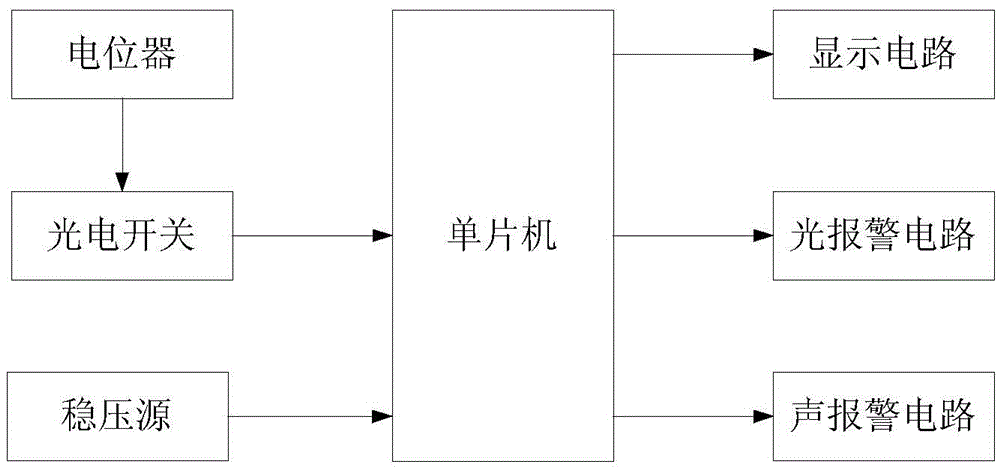
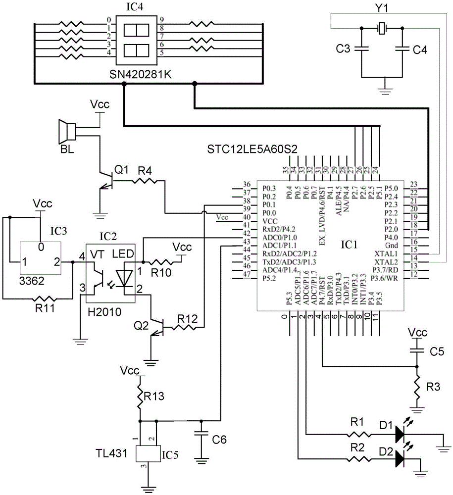
[0034] Specific implementation mode one: the following combination Figure 1 to Figure 3 Describe this embodiment, the miniature infrared photoelectric type drip alarm that shows the drip speed described in this embodiment, it comprises single-chip microcomputer, potentiometer, photoelectric switch, stabilized voltage source, display circuit, light alarm circuit and sound alarm circuit;

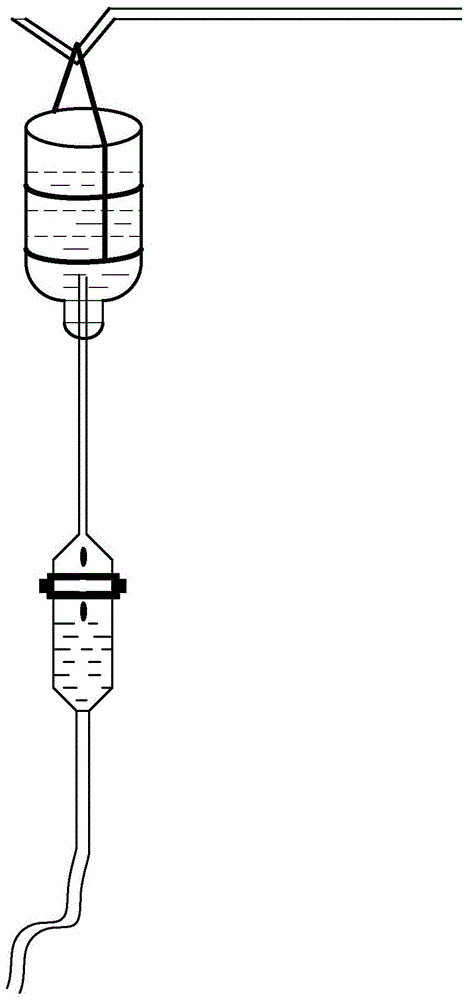
[0035] The photoelectric switch is a U-shaped structure, and the relative positions on the inner sides of the U-shaped structure are the transmitting end and the receiving end respectively. The emitting end is equipped with a light-emitting diode LED, and the receiving end is equipped with a photosensitive transistor VT. On the wall, the light-emitting diode LED and the phototransistor VT are respectively located on the opposite sides of the drip gourd;

[0036] The photoelectric switch collects the drip passing information, and the signal output terminal of the photoelectric switch is connec...


PUM


Abstract

The invention discloses a mini infrared photoelectric intravenous drip alarm device capable of displaying the intravenous drip speed, and belongs to the field of medical assistance. The mini infrared photoelectric intravenous drip alarm device aims at solving the problem that an existing infusion monitoring technology is not suitable for popularization. The mini infrared photoelectric intravenous drip alarm device comprises a single-chip microcomputer, a potentiometer, a photoelectric switch, a stable voltage source, a display circuit, a light alarm circuit and a sound alarm circuit. The photoelectric switch is of a U-shaped structure, a transmitting end and a receiving end are arranged at the opposite positions of the two inner sides of the U-shaped structure respectively, the transmitting end is provided with an LED, the receiving end is provided with a phototriode VT, and the U-shaped photoelectric switch is clamped to the position, above the liquid level, of the outer side wall of a calabash-shaped intravenous drip cavity so that the LED and the phototriode VT can be located on the two opposite sides of the calabash-shaped intravenous drip cavity respectively. The photoelectric switch collects dripping liquid passing information and sends the dripping liquid passing information to the single-chip microcomputer, and the display circuit displays the dripping liquid passing information; or, when no dripping liquid passes, the light alarm circuit and the sound alarm circuit give sound and light alarms. The stable voltage source is used for stabilizing a power supply of the single-chip microcomputer. The potentiometer is used for adjusting the dripping liquid collecting sensitivity.

Description

technical field [0001] The invention relates to an automatic monitoring device for a drip process in a hospital and a family, and belongs to the field of medical assistance. Background technique [0002] Medical intravenous infusion is an important treatment method in clinical medicine. Most of the drip methods use the principle of gravity. The medicine bottle or bag is hung on the drip stand, and the medicine in the bottle will drip down. During the infusion process, guardians are required to observe the speed and process of infusion. Since the infusion time cannot be accurately estimated, during the infusion process, the accompanying personnel need to pay attention to the remaining amount of the liquid medicine at any time. After a long time, they are very tired, especially at night, which is more common, which brings tension and stress to the patient and the accompanying personnel. Fatigue and many inconveniences. Therefore, Drip has the following limitations: [0003]...

Claims


Application Information

Patent Timeline
Patent Type & Authority Applications(China)
IPC IPC(8): A61M5/168
CPCA61M5/1689A61M5/172A61M2205/18
Inventor 原崧育原桂彬
Owner HARBIN INST OF TECH
Why Eureka
Try Eureka