Line-sweeping airflow slurry nozzle

A nozzle and airflow technology, applied in the field of online swept jet airflow slurry nozzles, can solve the problems of affecting the filling quality, increasing the hidden danger of underground mining, uneven concentration, etc. Effect

Inactive Publication Date: 2018-01-16
邓代强 +2
View PDF5 Cites 0 Cited by
  • Summary
  • Abstract
  • Description
  • Claims
  • Application Information

AI Technical Summary

Problems solved by technology

In general, in order to ensure the slurry-making effect of the tailings mortar, the tailings mortar is usually stirred pneumatically by the nozzle of the point jet flow, and the sand release operation is carried out after the mixing is uniform. Occasionally, there will be uneven concentration of the slurry. With the increase of the injection distance, the point jet flow basically changes from a point to a conical shape, and the contact surface with the object is basically a circle, so there is a certain force reduction effect. It will be affected, and the impact force of the circular jet surface is difficult to stir up the tightly agglomerated massive tailings, which will affect the stability of the filling concentration. At the same time, this method is time-consuming when emptying the container, and sometimes it will cause tailings Residue, cleaning is not clean, so the concentration fluctuation range of the tailing mortar is increased, which will seriously affect the filling quality, greatly increase the safety hazards of underground mining, cause waste of cementitious materials, and increase the cost of filling operations. Therefore, it is urgently needed at present An effective device for processing to achieve ideal slurry making and cleaning effects, that is, uniform and rapid mixing of tailings mortar and reduction of tailings deposition

Method used


Image

  • Line-sweeping airflow slurry nozzle
  • Line-sweeping airflow slurry nozzle
  • Line-sweeping airflow slurry nozzle

Examples


Embodiment Construction

[0016] The present invention will be further described below in conjunction with the accompanying drawings and embodiments.

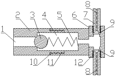
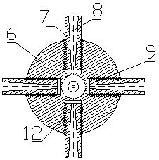
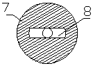
[0017] Referring to the accompanying drawings, this embodiment includes a housing 2, a steel ball 3, a spring 5, a nozzle seat 6 and a nozzle 7, the housing 2 is provided with an air inlet 1 and an air chamber 4, and the steel ball 3 and the spring 5 are installed In the air chamber 4, one end of the spring 5 is connected to the housing 2, and the other end is connected to the steel ball 3. When the high-pressure air passes through the air inlet 1, the steel ball 3 is pushed away and enters the air chamber 4. The opening and closing of the steel ball 3 The state is controlled by the spring 5. If there is no high-pressure gas supply, the steel ball 3 is pushed to the closed state by the spring 5; the nozzle seat 6 is installed at the end of the housing 2 and communicates with the air chamber 4; the nozzle 7 is Four are evenly distributed on the nozzle se...


PUM


Abstract

A linear spreading airflow slurry making nozzle comprises a shell, a steel ball, a spring, a nozzle base and nozzle bodies. An air inlet and an air chamber are formed in the shell. The steel ball and the spring are installed in the air chamber, one end of the spring is connected with the shell, and the other end of the spring is connected with the steel ball. When passing the air inlet, high-pressure air ejects the steel ball and then enters the air chamber, the open and closed states of the steel ball are controlled by the spring, and if no high-pressure air is supplied, the steel ball is ejected by the spring to be in a closed state. The nozzle base is installed at the end of the shell and communicated with the air chamber. The two or more nozzle bodies are evenly distributed on the nozzle base along the circumference, nozzle holes of the nozzle bodies are of a flat structure, and a cut rubber gasket is arranged at an inlet of each nozzle hole. By means of the linear spreading airflow slurry making nozzle, uniform tailing slurry can be quickly and efficiently prepared, the cleaning effect is remarkable, and the slurry making nozzle is convenient to machine, simple in structure and low in manufacturing cost.

Description

technical field [0001] The invention relates to a nozzle, in particular to a line-sweeping airflow slurry-making nozzle. Background technique [0002] In the process of making tailing mortar, in order to stir the filling tailing mortar evenly and avoid excessive sand accumulation in the container, appropriate technical measures must be taken to achieve better mixing and sand cleaning effects. When using different devices, the manufacturing The uniformity and effectiveness of the slurry will vary. In general, in order to ensure the slurry-making effect of the tailings mortar, the tailings mortar is usually agitated pneumatically with the nozzle of the point jet flow, and the sand release operation is carried out after the mixing is uniform. Occasionally, the concentration of the slurry may be uneven. With the increase of the spray distance, the point jet flow basically changes from a point to a conical shape, and the contact surface with the object is basically a circle, so ...

Claims


Application Information

Patent Timeline
Patent Type & Authority Patents(China)
IPC IPC(8): B05B1/00B05B1/30B05B15/00
CPCB05B1/00B05B1/30B05B15/00
Inventor 邓代强邓代君易波
Owner 邓代强
Why Eureka
Try Eureka