Single hole cross jet slurry nozzle

A cross-shaped and nozzle technology, applied in the field of single-hole cross-shaped jet slurry nozzles, can solve the problems of affecting filling quality, increasing the fluctuation range of tailings slurry concentration, and waste of cementitious materials, avoiding large-scale sand accumulation and reducing Small blockage risk and effect of reducing filling cost

Inactive Publication Date: 2018-02-27
邓代强 +2
View PDF5 Cites 0 Cited by
  • Summary
  • Abstract
  • Description
  • Claims
  • Application Information

AI Technical Summary

Problems solved by technology

In general, in order to ensure the slurry-making effect of the tailings mortar, the tailings mortar is usually agitated pneumatically with the nozzle of the point jet flow, and the sand release operation is carried out after the mixing is uniform. Occasionally, the concentration of the slurry may be uneven. With the increase of the spray distance, the point jet flow basically changes from a point to a conical shape, and the contact surface with the object is basically a circle, so there is a certain force reduction effect, and the effect is It will be greatly affected. The impact force of the circular jet surface is difficult to disperse the tightly agglomerated massive tailings, so it will affect the stability of the filling concentration. At the same time, this method is time-consuming and energy-consuming when emptying the container. Usually, tailings residues are left, and the cleaning is not clean, so the concentration fluctuation range of tailings mortar is increased, which will seriously affect the filling quality, cause a great increase in underground mining safety hazards, cause waste of cementitious materials, and increase filling Operating cost, at this time, a convenient and efficient device is needed for processing to achieve the ideal slurry making and cleaning effect, that is, uniform and fast mixing of tailings mortar and reduction of tailings deposition

Method used


Image

  • Single hole cross jet slurry nozzle
  • Single hole cross jet slurry nozzle
  • Single hole cross jet slurry nozzle

Examples


Embodiment Construction

[0019] The present invention will be further described below in conjunction with the accompanying drawings and embodiments.

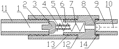
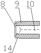
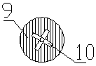
[0020] Referring to the accompanying drawings, this embodiment includes a housing 2, a one-way valve 3, a spring 7 and a nozzle 9, the housing 2 is provided with an air chamber 6 and a short-circuit 11 for connecting with the main air duct for air supply, The short-circuit 11 is provided with an air inlet 1; the one-way valve 3 and the spring 7 are installed in the air chamber 6, one end of the spring 7 is connected to the housing 2, and the other end is connected to the one-way valve 3, The one-way valve 3 is connected to the short circuit 11 installed in the housing 2, the one-way valve 3 is provided with a tail rod 5, and the tail rod 5 is located in the spring 7, when the high-pressure air passes through the air inlet 1 , the one-way valve 3 is pushed back into the air chamber 6, and the opening and closing state of the one-way valve 3 is controlled...


PUM


Abstract

A single-hole cross-shaped jet slurry-making nozzle comprises a casing, a non-return valve, a spring and a nozzle, wherein an air chamber and a pipe nipple are arranged in the casing, the pipe nipple is used for being connected with a main air pipe used for supplying air, and an air inlet hole is formed in the pipe nipple; the non-return valve and the spring are mounted in the air chamber, one end of the spring is connected with the casing, the other end of the spring is connected with the non-return valve, the non-return valve is connected with the pipe nipple mounted in the casing, and a tail rod is arranged on the non-return valve and located in the spring; when high-pressure air passes through the air inlet hole, the high-pressure air pushes the non-return valve open and then enters the air chamber; the open / closed state of the non-return valve is controlled by the spring; when no high-pressure air is supplied, the non-return valve is pushed by the spring to a closed state; and the nozzle is mounted on the casing and communicates with the air chamber, a notched rubber gasket is arranged in the nozzle, and a nozzle hole of the nozzle is cross-shaped. Through the single-hole cross-shaped jet slurry-making nozzle, uniform tailings slurry can be prepared fast and efficiently, and the effects of slurry making and blocky tailings hammering are remarkable.

Description

technical field [0001] The invention relates to a nozzle, in particular to a single-hole cross-shaped jet slurry-making nozzle. Background technique [0002] In the process of making tailing mortar, in order to stir the filling tailing mortar evenly and avoid excessive sand accumulation in the container, it is necessary to use some devices to achieve better mixing and sand cleaning effects. Therefore, appropriate technical measures must be taken, that is, different devices must be used to stir the tailing mortar. When different devices are used, the uniformity and effect of slurry making will be different. In general, in order to ensure the slurry-making effect of the tailings mortar, the tailings mortar is usually agitated pneumatically with the nozzle of the point jet flow, and the sand release operation is carried out after the mixing is uniform. Occasionally, the concentration of the slurry may be uneven. With the increase of the spray distance, the point jet flow basic...

Claims


Application Information

Patent Timeline
Patent Type & Authority Patents(China)
IPC IPC(8): B05B1/02B05B1/32
CPCB05B1/02B05B1/32
Inventor 邓代强邓代君易波
Owner 邓代强
Why Eureka
Try Eureka