Automatic battery core spot welding device and automatic spot welding method thereof

An automatic spot welding and electric core technology, applied in the direction of auxiliary devices, welding equipment, auxiliary welding equipment, etc., can solve the problems of high labor cost, low production efficiency, spot welding position deviation, etc., to achieve good product quality, improve efficiency, The effect of saving manpower

Active Publication Date: 2016-05-04
DONGGUAN AOHAI TECH CO LTD
View PDF5 Cites 23 Cited by
  • Summary
  • Abstract
  • Description
  • Claims
  • Application Information

AI Technical Summary

Problems solved by technology

At present, manual spot welding is usually used to process the cells one by one, and the metal sheets are spot welded to the two poles of the cell. This manual spot welding processing method has low production efficiency and high labor costs, and multiple battery cells are spot welded. In this case, the fixation effect of the spot welding position is not good, which will easily lead to deviation of the spot welding position or false welding, which will affect the normal power supply of the battery pack. The product quality is greatly affected by the individual proficiency and level of the operator. production demand

Method used


Image

  • Automatic battery core spot welding device and automatic spot welding method thereof
  • Automatic battery core spot welding device and automatic spot welding method thereof
  • Automatic battery core spot welding device and automatic spot welding method thereof

Examples


Embodiment Construction

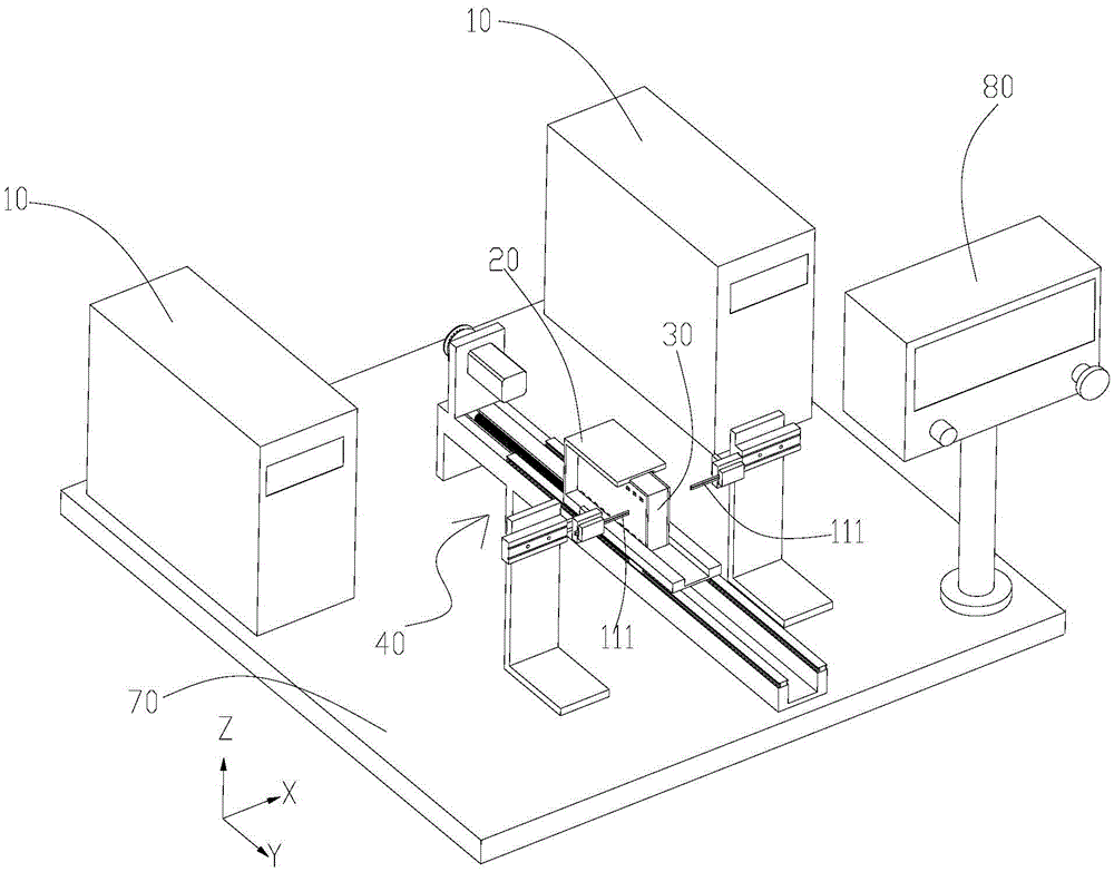
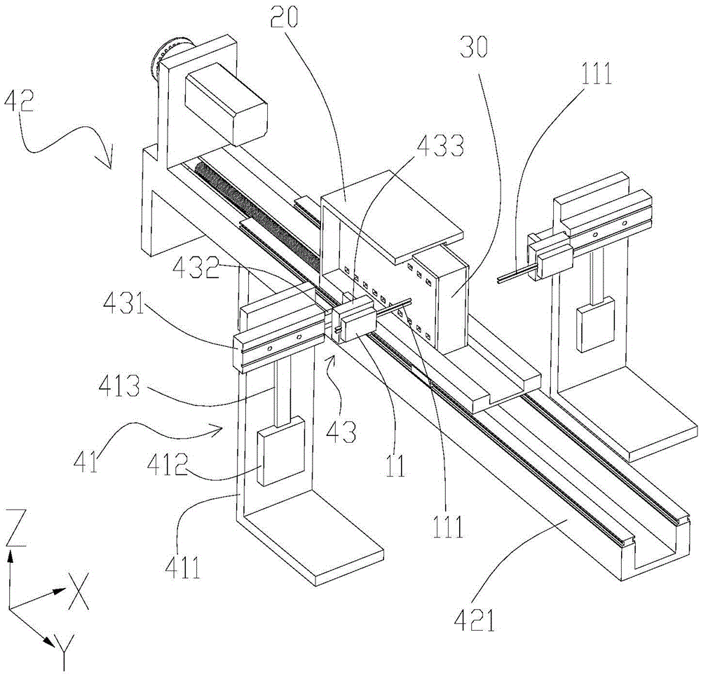
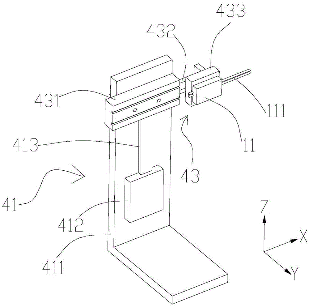
[0038] Such as figure 1 As shown, an automatic spot welding device for batteries is placed on a table top 70, and includes spot welding equipment 10 with two welding heads 111 symmetrically arranged, a spot welding jig 30 for placing a single battery cell to be welded, and a fixed point The fixture holder 20 of the welding fixture 30 can drive the fixture holder 20 and the welding head 111 to move relatively in three dimensions in the spot welding process (such as Figure 1-3 Shown X, Y, Z three-dimensional direction), make welding head 111 displacement device 40 that welds spot welding hole 321 on corresponding spot welding tool 30; 1. The displacement devices 40 realize the coordination of their work processes through the programming of the PLC control system. The wires connected to each other by electrical communication are hidden under the table 70, and the PLC control system is connected to the control panel 80. In this embodiment, the electric welding equipment 10 inclu...


PUM


Abstract

The invention discloses an automatic battery core spot welding device and an automatic spot welding method thereof. The automatic battery core spot welding device comprises two spot welding devices, a spot welding fixture, a fixture clamping seat, a displacement device and a PLC control system; welding heads of the spot welding devices are symmetrically arranged, the spot welding fixture is used for containing a battery core monomer to be welded, the fixture clamping seat is used for fixing the spot welding fixture, and the displacement device is arranged between the two welding heads and can drive the fixture clamping seat and the welding heads to do relative three-dimensional movement to enable the welding heads to correspond to spot welding holes formed in the spot welding fixture to perform welding in the spot welding process; the PLC control system can enable the spot welding devices and the displacement device to coordinately work; the spot welding fixture can accurately position and fix different numbers of the battery cores to ensure that electrodes and metal sheets of the battery cores to be closely attached; through the displacement which moves in the X, Y and Z three-dimensional directions to enable the welding heads to correspond to the spot welding holes formed in the spot welding fixture to perform welding, automation is completely achieved in the whole spot welding process, manpower is saved, the efficiency is improved, and it is guaranteed the quality of the products processed through spot welding is good without being influenced by individual level of operators.

Description

technical field [0001] The invention relates to mobile power supply production and processing equipment, in particular to an automatic spot welding device for electric cores and an automatic spot welding method thereof. Background technique [0002] In the production and processing of mobile power supplies, it is necessary to combine single cells into a battery pack. One of the most important steps is to spot weld metal sheets on the positive and negative electrodes of multiple cells to achieve parallel expansion of batteries. At present, manual spot welding is usually used to process the cells one by one, and the metal sheets are spot welded to the two poles of the cell. This manual spot welding processing method has low production efficiency and high labor costs, and multiple battery cells are spot welded. In this case, the fixation effect of the spot welding position is not good, which will easily lead to deviation of the spot welding position or false welding, which will...

Claims


Application Information

Patent Timeline
Patent Type & Authority Applications(China)
IPC IPC(8): B23K37/04B23K37/047B23K37/02B23K37/00
CPCB23K37/00B23K37/02B23K37/0435B23K37/047B23K2101/36
Inventor 刘昊欧阳军程元赖虹敏林礼周鹏陈永新严艳松
Owner DONGGUAN AOHAI TECH CO LTD
Why Eureka
Try Eureka