Injection molding machine

An injection molding machine, injection molding technology, applied in the direction of electrical components, circuits, connections, etc., to solve the problem of impossible to process two cable ends together, impossible to automatically perform this test, etc.

Inactive Publication Date: 2016-05-04
CURTI COSTR MECCANICHE
View PDF5 Cites 7 Cited by
  • Summary
  • Abstract
  • Description
  • Claims
  • Application Information

AI Technical Summary

Problems solved by technology

[0013] A disadvantage of the known device is that it is not possible to perform such tests automatically and without interrupting the production cycle to carry out such tests
[0014] Another disadvantage of the known device is that it is difficult or basically impossible to process two cable ends together, in fact, in the described device, due to the shape of the mold that requires a balanced and correct injection, it is generally not possible to Injection of the same material into cavities of different sizes and geometries

Method used


Image

  • Injection molding machine
  • Injection molding machine
  • Injection molding machine

Examples


Embodiment Construction

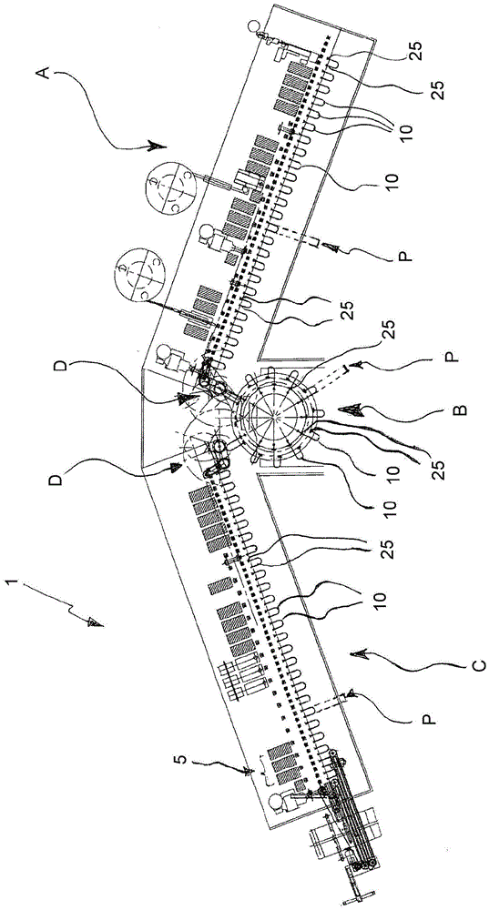
[0038] figure 1 Shown is a partial plan view of an embodiment of a production apparatus 1 for the production (overmolding) of elongated flexible members 10, preferably cables, said apparatus comprising a first section A for preparing at least one end of the cable; molding section B, by means of which section B injects thermoplastic material on at least one end of the cable; and section C, wherein the unprocessed end in section A is further processed processing. The apparatus 1 of the invention is characterized in that it also comprises means for testing the cable 10 before outputting the cable 10 from the apparatus, holding means for holding both ends of the cable in all processing stations, and holding means for removing said ends from a section. A moving device that holds the device for moving the device to the next section.

[0039] As mentioned above, the apparatus of the present invention is used for overmolding connecting cable ends, live or otherwise, in particular, o...


PUM


Abstract

The invention relates to an injection molding machine. The injection molding machine comprises multiple molds (3) and injection molders (6) for all the molds; and the molds and the corresponding injection molders are mounted on a platform (4), and rotate with the platform.

Description

[0001] This application is a divisional application of an invention patent application with the application number CN200980163461.8 (PCT / IT2009 / 000578), the application date being December 24, 2009, and the invention title being "equipment and method for manufacturing connecting cables". technical field [0002] The invention relates to a device for manufacturing connecting cables. More specifically, the present invention relates to an apparatus and method for making and overmolding a connector on at least one end of a length of flexible cable, the cable having at least one connector end. Background of the invention [0003] In the description of the present invention, the term connection cable means a cable, in particular a cable equipped with connection means at one or both ends, especially a power connector, and by overmolding the At least one of the two ends of the cable is configured in thermoplastic material. In the following description, only the manufacture of the c...

Claims


Application Information

Patent Timeline
Patent Type & Authority Applications(China)
IPC IPC(8): B29C45/06B29C45/14H01R43/00
CPCB29C45/06B29C45/14H01R43/00
Inventor E·博卡托
Owner CURTI COSTR MECCANICHE
Why Eureka
Try Eureka