Glass bead conveying device of computer embroider machine

An embroidery machine and glass bead technology, which is applied to the mechanism of embroidery machines, embroidery machines, automatic control embroidery machines, etc., can solve the problems of glass beads being easily stuck, high cost, complex structure, etc., and achieve good bead delivery reliability , low cost and simple structure

Inactive Publication Date: 2016-05-04
应建忠
View PDF10 Cites 7 Cited by
  • Summary
  • Abstract
  • Description
  • Claims
  • Application Information

AI Technical Summary

Problems solved by technology

The bead-feeding impeller, bead-feeding control mechanism, feed mechanism and bead-feeding turntable are respectively driven by independent motors, with complex structure and high cost, and glass beads are easy to get stuck on the bead-feeding turntable

Method used


Image

  • Glass bead conveying device of computer embroider machine
  • Glass bead conveying device of computer embroider machine
  • Glass bead conveying device of computer embroider machine

Examples


Embodiment Construction

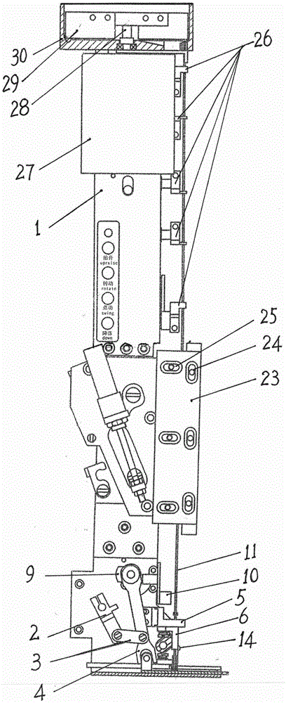
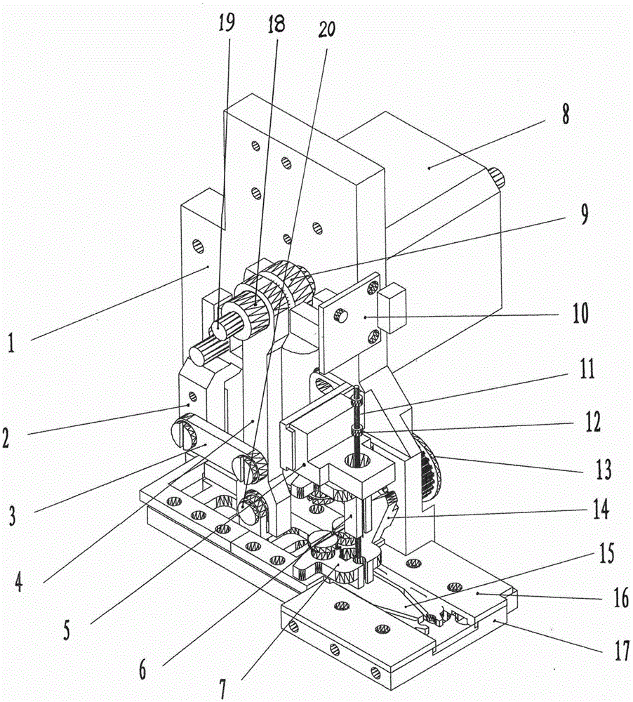
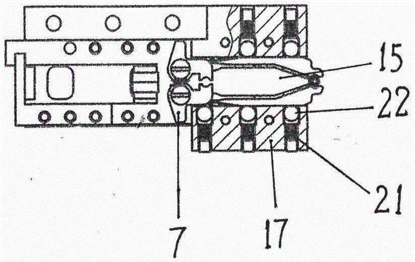
[0013] Such as figure 1 The glass bead feeding device of the computerized embroidery machine shown includes a mounting plate 1, a bead feeding cylinder 30, a bead feeding impeller 29, a bead feeding track 11, a bead feeding control mechanism, and a feeding mechanism. The upper end of the plate 1 and the bottom of the bead barrel 30 are provided with a bead outlet hole, and the upper end of the bead delivery track 11 is located directly below the bead outlet hole. Above, the bead sending impeller 29 is located in the bead barrel 30 and is fixedly installed on the end of the bead feeding motor 28 shaft to stir the glass beads 12 so that the glass beads 12 can be reliably output from the bead outlet; the feeding mechanism is composed of the bottom plate 17, the feeding motor 8. Bead push plate 15, push plate feed mechanism and control signal device; , the two ends of the connecting rod 3 are respectively hinged with the rocker 2 and the rocker 4, the upper end of the rocker 4 is...


PUM


Abstract

The invention relates to a glass bead conveying device of a computer embroider machine. The glass bead conveying device comprises a mounting plate, a bead material cylinder, a bead conveying impeller, a bead conveying track, a bead conveying control mechanism and a feeding mechanism, wherein the bead material cylinder is fixedly mounted at the upper end part of the mounting plate, the bottom part of the bead material cylinder is provided with a bead outlet, the upper end of the bead conveying track is located directly below the bead outlet, the bead conveying impeller is located in the bead material cylinder and is fixedly mounted at the end part of a bead conveying motor shaft; the feeding mechanism consists of a bottom plate, a feeding motor, a bead pushing plate, a pushing plate feeding mechanism and a control signal device; an upper elastic bead embracing block and a lower elastic bead embracing block are arranged at the outside of the bead conveying track at the upper side of the bead pushing plate, a switch striking block is arranged between the upper elastic bead embracing block and the lower elastic bead embracing block, a glass bead is conveyed into the bead conveying track through a bead conveying motor, and is conveyed into an elastic clamping opening of the bead pushing plate through the upper elastic bead embracing block and the lower elastic bead embracing block, and bead embroidery is realized under the control of the feeding motor; the glass bead feeding device is simple in structure, low in cost, good in bead conveying reliability, and suitable for a bead embroidery conveying device of the computer embroider machine.

Description

technical field [0001] The invention belongs to embroidery equipment, in particular to a bead feeding device for computerized embroidery machines. The invention is suitable for the bead embroidery feeding device of the computerized embroidery machine. Background technique [0002] In the bead embroidery process of computerized embroidery machines, the glass beads are transported directly under the embroidery needle by the feeding device, and its structure includes a mounting plate, a bead barrel, a bead feeding impeller, a bead feeding track, a bead feeding control mechanism, and a feeding mechanism. The bead material cylinder is fixedly installed on the upper end of the mounting plate. The bottom of the bead material cylinder is provided with a bead outlet hole. The upper end of the bead delivery track is located directly below the bead outlet hole. The bead outlet hole falls on the bead feeding track, and is sent to the feeding mechanism by the bead feeding turntable, and...

Claims


Application Information

Patent Timeline
Patent Type & Authority Applications(China)
IPC IPC(8): D05C7/08D05C13/00
CPCD05C7/08D05C13/00
Inventor 应建忠
Owner 应建忠
Why Eureka
Try Eureka