An efficient and compact double-row automatic piling device
What is Al technical title?
Al technical title is built by PatSnap Al team. It summarizes the technical point description of the patent document.
A piling device, compact technology, applied in the direction of sheet pile wall, building, foundation structure engineering, etc., can solve the problems of not being able to tilt the piling, low safety factor, high safety factor, etc., to achieve improved working capacity, light weight, and improved safety factor Effect
Inactive Publication Date: 2017-09-29
QINGDAO UNIV OF SCI & TECH
View PDF6 Cites 0 Cited by
Summary
Abstract
Description
Claims
Application Information
AI Technical Summary
This helps you quickly interpret patents by identifying the three key elements:
Problems solved by technology
Method used
Benefits of technology
Problems solved by technology
[0005] The purpose of the present invention is to overcome the shortcomings of existing piling machines that cannot be tilted for piling, inconvenient to use, too bulky, loud in noise, low in safety factor, and low in piling efficiency. A piling device and piling method with compact structure, convenient use, small volume, high safety factor, high piling quality and high piling efficiency
Method used
Image
Click on the blue label to locate the original text in one second.
Reading with bidirectional positioning of images and text.
Examples
Embodiment Construction
[0027] Specific embodiments of the present invention will be described in detail below. It should be understood that the specific embodiments described here are only used to illustrate and explain the present invention, and are not intended to limit the present invention.
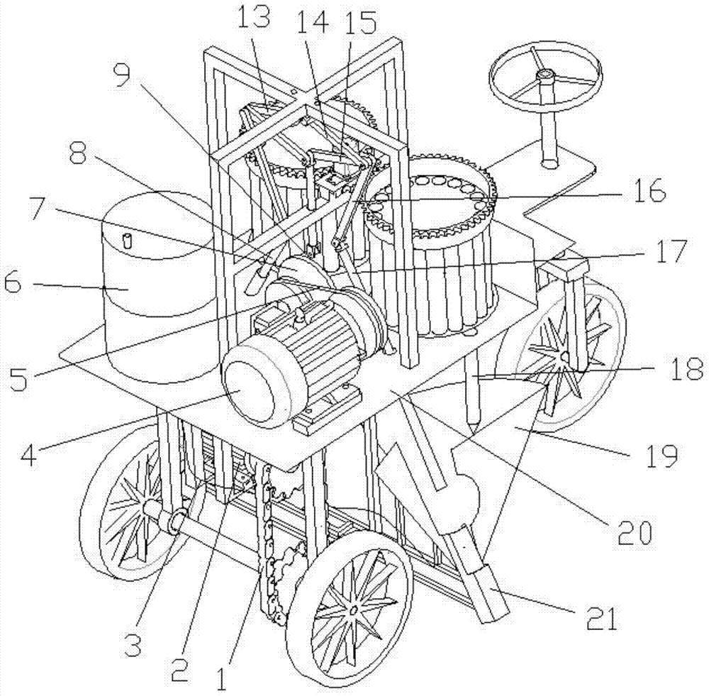
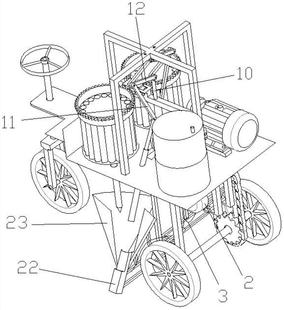
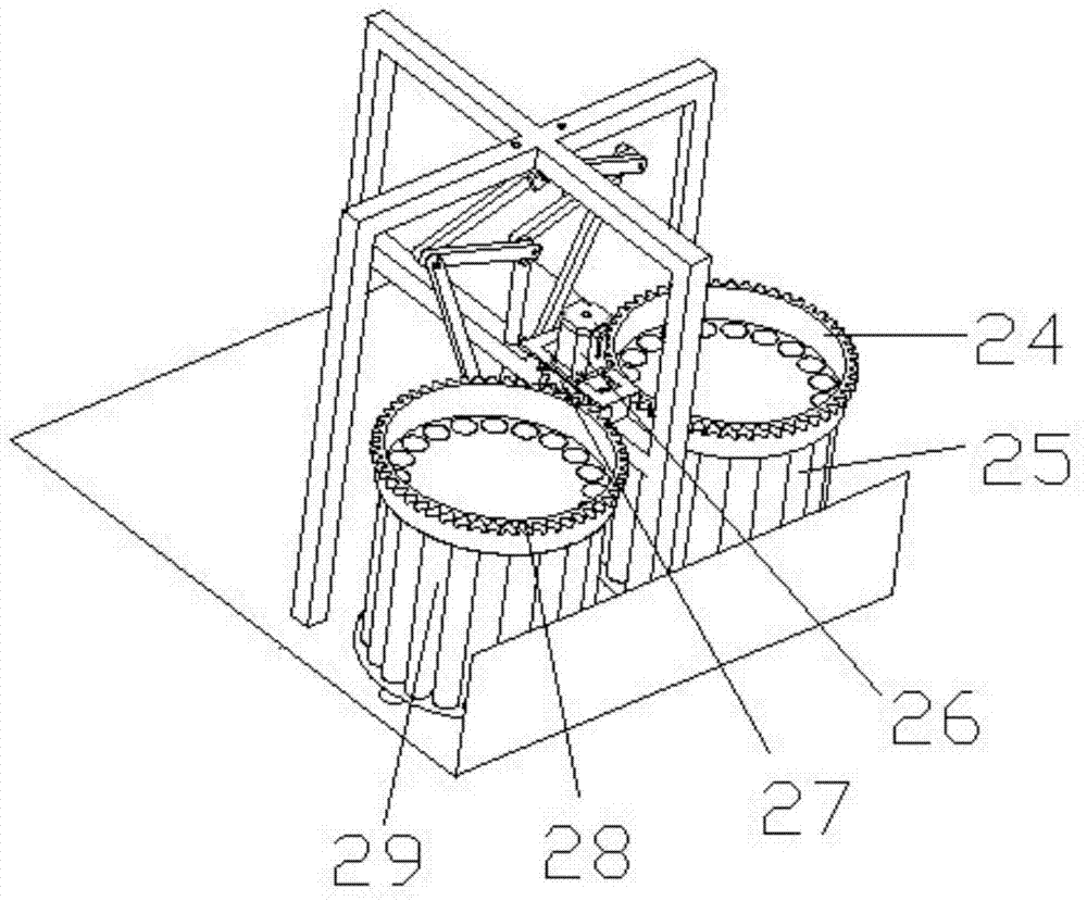
[0028] Such as figure 1 As shown, a high-efficiency and compact double-row automatic piling device of the present invention includes a chain 1, a No. Rod 8, connecting rod Ⅰ 9, vertical rod 10, connecting rod Ⅱ 11, rocker A 12, rocker B 13, rocker C 14, rocker D 15, connecting rod Ⅲ 16, impact rod Ⅱ 17, wood pile 18, No. Ⅱ transition chute 19, rack 20, No. Ⅱ 60° positioning tube 21, No. 1 60° positioning tube 22, No. 1 transition chute 23, No. 1 barrel gear 24, No. Ⅰ Barrel 25, stepper motor 26, gear 27 for stepper motor, gear 28 for No. II barrel, No. II barrel 29.
[0029] Turn on No. II motor 2, drive the piling device forward through the chain and the sprocket, and move the piling device to the posit...
PUM
Abstract
The invention discloses an efficient and compact double-row automatic piling device. The piling device comprises a rack, a power unit, a piling mechanism, a water storage barrel, a storage device, a transition chute and a 60-degree positioning tube, wherein the piling mechanism comprises a motor I, a belt pulley group, a crank, a connecting rod I, a vertical rod, a four-bar mechanism, a connecting rod II, a connecting rod III, a knocking rod I and a knocking rod II; the storage device comprises a barrel, a gear for the barrel, a stepping motor, a gear for the stepping motor and a discharging hole; the power unit comprises a motor II, a chain wheel and a chain; and the rack comprises a steering wheel, a piling mechanism support frame, a supporting plate, a transition chute connecting rack, wheels and a brake. By the efficient and compact double-row automatic piling device, wood piles can be placed automatically, and are inclined until the angle between each wood pile and the ground is 60 degrees during piling, and simultaneous piling of two sides of the piling device is implemented. The efficient and compact double-row automatic piling device is convenient to use, and piling efficiency, piling quality and safety factors are greatly improved.
Description
technical field [0001] The invention belongs to the field of piling machinery, and in particular relates to an efficient and compact double-row automatic piling device. Background technique [0002] Pile drivers are widely used in agricultural production, especially in the construction of agricultural greenhouses. Usually, farmers use hammers to drive piles manually, or use electric drills to drill holes in the ground first, and then drive into wooden piles, but the labor intensity for farmers is quite high. The labor intensity of drilling piles with an electric drill is small, but the friction between the ground and the wooden piles is relatively small, and the wooden piles are easily pulled out of the ground when encountering strong winds. Some greenhouses have to disassemble and reinstall wooden piles every year, so piling is a labor-intensive and relatively frequent work for farmers. [0003] Some existing engineering piling machines basically use heavy hammers to driv...
Claims
Application Information
Patent Timeline
Application Date:The date an application was filed.
Publication Date:The date a patent or application was officially published.
First Publication Date:The earliest publication date of a patent with the same application number.
Issue Date:Publication date of the patent grant document.
PCT Entry Date:The Entry date of PCT National Phase.
Estimated Expiry Date:The statutory expiry date of a patent right according to the Patent Law, and it is the longest term of protection that the patent right can achieve without the termination of the patent right due to other reasons(Term extension factor has been taken into account ).
Invalid Date:Actual expiry date is based on effective date or publication date of legal transaction data of invalid patent.