
Novel high-temperature magnetic drive pump

A magnetic pump, high temperature technology, applied in the direction of pumps, pump devices, pump components, etc., can solve the problems of pumps not working normally, complex structure, damage, etc., and achieve the effect of avoiding excessive shaft temperature, increasing contact area, and uniform heat dissipation

Inactive Publication Date: 2016-05-04
JIANGSU HANNA PUMP IND CO LTD
View PDF4 Cites 2 Cited by
  • Summary
  • Abstract
  • Description
  • Claims
  • Application Information

AI Technical Summary

Problems solved by technology

In coal-to-ethylene glycol methanol and other process devices, the centrifugal chemical process high-temperature magnetic pump is used to transport media such as ethylene glycol and methanol. The common chemical pumps on the market have complex structures, high costs, poor sealing performance, and are not easy to operate. Disassembly is not convenient for later maintenance, and the maintenance period is long. Considering the high-temperature corrosive substances transported by the chemical high-temperature magnetic pump, it is highly corrosive to the flow-passing parts of the pump, and the high-temperature medium transported by the high-temperature magnetic pump will transfer A large amount of heat will increase the working temperature of the pump. Excessively high temperature will not only cause serious wear or damage to the rolling bearing, but also cause demagnetization of the magnet, so that the pump cannot work normally.

Method used


Image

  • Novel high-temperature magnetic drive pump

Examples


Embodiment 1

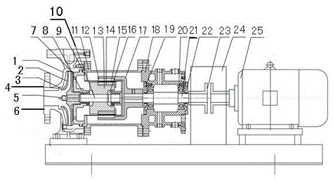
[0015] Embodiment 1, with reference to figure 1 , is a new type of high-temperature magnetic pump, including a motor 25, a pump body 1, a pump cover 7, an impeller 2, a bearing housing 18 and a pump inlet 6 arranged at the front end of the pump body 1, and is characterized in that the output shaft of the motor 25 The end is connected with the drive shaft 21 through a coupling 23, the coupling 23 is covered with a coupling cover 24, the pump body 1 is provided with a pump body mouth ring 3, and the impeller 2 is set on the impeller. The bottom of the wheel shaft 10 is provided with the impeller nut 5 for locking the impeller 2 at the bottom of the impeller shaft 10, the impeller mouth ring 4 is arranged on the impeller 2, and the inner magnetic steel 13 and the outer magnetic steel are fixed on the end of the impeller shaft 10. 17 and spacer sleeve 9, a magnetic sheet 12 is provided between the inner magnetic steel 13 and the outer magnetic steel 17, and a positioning sleeve 14...

Embodiment 2

[0016] Embodiment 2, in the novel high-temperature magnetic pump described in Embodiment 1: several rectangular vanes are arranged outside the bearing housing 18, bearing glands 19 are arranged in the bearing housing 18, and bearing glands 19 are provided with Labyrinth seal and dust disc.

Embodiment 3

[0017] Embodiment 3, in the novel high-temperature magnetic pump described in Embodiment 1: a bearing housing cover plate 22 is provided outside the bearing housing 18 .


PUM


Abstract

The invention relates to a novel high-temperature magnetic drive pump which comprises a motor, a pump body, a pump cover, an impeller, a bearing box and a pump inlet formed in the front end of the pump body. The novel high-temperature magnetic drive pump is characterized in that the end of an output shaft of the motor is connected with a transmission shaft through a coupling; the coupling is sleeved with a coupling guard; a casing wear ring is arranged on the pump body; the lower portion of an impeller shaft is sleeved with the impeller; an impeller nut for locking the impeller is arranged at the bottom of the impeller shaft; an impeller wear ring is arranged on the impeller; inner magnetic steel, outer magnetic steel and an isolation sleeve are fixed to the end of the impeller shaft; a magnetic sheet is arranged between the inner magnetic steel and the outer magnetic steel and provided with a locating sleeve and a sheath; a graphite shaft sleeve is arranged between the impeller shaft and the pump cover; the bearing box is arranged on the pump cover; and a water jacket is arranged outside the bearing box.

Description

technical field [0001] The invention relates to a chemical pipeline process pump, in particular to a novel high-temperature magnetic pump. Background technique [0002] With the development of society, in modern life, chemical products are inseparable almost anytime and anywhere. From material life such as clothing, food, housing and transportation to spiritual life such as culture, art and entertainment, chemical products are required to serve them. In coal-to-ethylene glycol methanol and other process devices, the centrifugal chemical process high-temperature magnetic pump is used to transport media such as ethylene glycol and methanol. The common chemical pumps on the market have complex structures, high costs, poor sealing performance, and are not easy to operate. Disassembly is not convenient for later maintenance, and the maintenance period is long. Considering the high-temperature corrosive substances transported by the chemical high-temperature magnetic pump, it is h...

Claims


Application Information

Patent Timeline
Patent Type & Authority Applications(China)
IPC IPC(8): F04D13/06F04D7/06F04D29/044F04D29/62F04D29/58F04D29/046F04D29/08F04D29/06
CPCF04D13/06F04D7/06F04D29/044F04D29/0462F04D29/061F04D29/086F04D29/586F04D29/628
Inventor 冯长青何佳王满亮
Owner JIANGSU HANNA PUMP IND CO LTD
Learn More