Mechanical sealing structure for centrifugal pump

A centrifugal pump and mechanical seal technology, which is applied to the components, pumps, and pump elements of the pumping device for elastic fluids, and can solve the problems of damage to the outer coating, dimensional changes, wear, etc., to reduce the cost of spare parts and The effect of maintenance cost, elimination of hidden dangers of safety and environmental protection, and reduction of labor intensity

Inactive Publication Date: 2016-05-04
HENAN SHENMA NYLON CHEM
View PDF6 Cites 0 Cited by
  • Summary
  • Abstract
  • Description
  • Claims
  • Application Information

AI Technical Summary

Problems solved by technology

In actual production, it is found that the original seal structure of the mechanical seal is not suitable for the sealing form of the actual working condition. When the pump starts or stops, the front pair of the original double-face mechanical seal will crack or break; the material of the dynamic and static rings is not suitable for the mixed medium of particles. Faster wear and tear; the material of the mechanical seal O-ring is prone to dimensional changes, wear, and damage to the outer coating

Method used


Image

  • Mechanical sealing structure for centrifugal pump
  • Mechanical sealing structure for centrifugal pump

Examples


Embodiment Construction

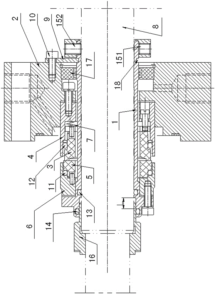
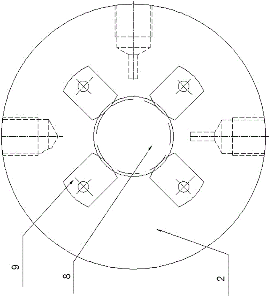
[0023] The specific implementation manners of the present invention will be described in detail below in conjunction with the accompanying drawings.

[0024] Such as figure 1 and figure 2 As shown, the mechanical seal structure for a centrifugal pump of the present invention includes a static ring 3, a moving ring 5, a mechanical seal seat 2 and a shaft sleeve 1 fixedly sleeved on the pump shaft 8, and the static ring 3 is gapped between On the shaft sleeve 1, the moving ring 5 is sleeved on the shaft sleeve 1, and the shaft sleeve 1 is fixedly provided with a moving ring sealing seat 6 for limiting the moving ring 5 therein. The ring seal seat 6 is in transmission connection with the pump shaft 8, and the moving ring seal seat 6 can drive the moving ring 5 within the limit to rotate together with the pump shaft 8, and the gap between the machine seal seat 2 is set on the shaft On the cover 1, the machine seal seat 2 is fixed relative to the pump body.

[0025] A static ri...


PUM


Abstract

The invention discloses a mechanical sealing structure for a centrifugal pump. The mechanical sealing structure comprises a fixed ring, a movable ring, a mechanical sealing seat and a shaft sleeve, wherein the shaft sleeve is fixedly arranged on a pump shaft in a sleeving manner, a movable ring sealing seat allowing the movable ring to be limited in the movable ring sealing seat is arranged in the shaft sleeve in a sleeving manner, a gap of the mechanical sealing seat is arranged on the shaft sleeve in a sleeving manner, a fixed ring sealing seat allowing the fixed ring to be limited in the fixed ring sealing seat is arranged between the mechanical sealing seat and the shaft sleeve, an axial spring is arranged in the fixed ring sealing seat, and the spring enables the fixed ring to be abutted against the movable ring; radial positioning plates are arranged at the rear end of the mechanical sealing seat; a shaft head loop which is in axial and movable connection with the pump shaft is arranged on a shaft shoulder of the pump shaft in a sleeving manner. According to the mechanical sealing structure disclosed by the invention, a double end surface mechanical seal is changed into a single end surface mechanical seal, and a leakage problem caused by the fracture of a mechanical sealing friction pair is solved, influence of particle media on a movable ring sealing surface and a fixed ring sealing surface is reduced, the service cycle of the pump is prolonged, the expense of spare parts is reduced, and the repairing cost is reduced.

Description

technical field [0001] The invention belongs to the technical field of mechanical seals, in particular to a mechanical seal structure for centrifugal pumps. Background technique [0002] In the production of hexamethylenediamine, the pressure of the reaction system is high, and the conveying medium is granular mixed reaction materials, which may easily cause mechanical seal leakage, pump noise and vibration damage to the conveying pump used for material reflux, once it occurs, it will directly cause The reaction materials will leak completely within 30 minutes, causing parking and major accidents, which will cause great hidden dangers to stable production and safety and environmental protection requirements. Traditionally designed double-end machine-sealed high-pressure centrifugal pumps are used in the conventional production of hexamethylenediamine, with internal flushing and external cooling flushing systems. In actual production, it is found that the original seal struc...

Claims


Application Information

Patent Timeline
Patent Type & Authority Applications(China)
IPC IPC(8): F04D29/12F04D29/70F04D29/044F04D29/02
CPCF04D29/126F04D29/026F04D29/044F04D29/708
Inventor 张秋生高先明王现林黄敏郭强晋文涛马高远赵时超
Owner HENAN SHENMA NYLON CHEM
Why Eureka
Try Eureka