Floating caliper disc brake with permanent magnet

A disc brake and permanent magnet technology, applied in the direction of brake type, axial brake, brake components, etc., can solve the problems of slow brake response speed and different wear conditions, and achieve the effect of smooth coordination

Inactive Publication Date: 2016-05-04
CHONGQING ZETIAN AUTO PARTS
View PDF0 Cites 2 Cited by
  • Summary
  • Abstract
  • Description
  • Claims
  • Application Information

AI Technical Summary

Problems solved by technology

[0004] The present invention intends to provide a floating caliper disc brake with permanent magnets to solve the problems of dif

Method used


Image

  • Floating caliper disc brake with permanent magnet

Examples


Embodiment Construction

[0013] The present invention will be described in further detail below by means of specific embodiments:

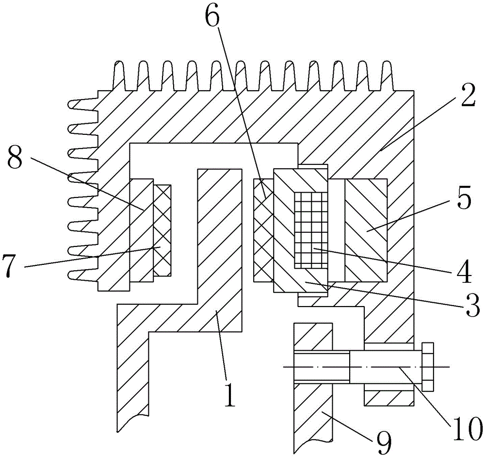
[0014] The reference signs in the accompanying drawings include: brake disc 1, brake caliper 2, armature 3, excitation coil 4, permanent magnet 5, movable brake block 6, fixed brake block 7, brake pad 8, Brake bracket 9, guide pin 10.

[0015] The embodiment is basically as attached figure 1 Shown: a floating caliper disc brake with permanent magnets, including a brake caliper 2, which floats across both sides of the brake disc 1, and is located on the left side of the brake disc 1 when braking. The fixed brake block 7 and the movable brake block 6 located on the right side of the brake disc 1 respectively clamp the brake disc 1 from both sides, and the brake disc 1 realizes rapid braking under the action of the friction force of both.

[0016] The right side of the brake caliper 2 is respectively provided with a first groove and a second groove, and the first groove is...


PUM


Abstract

The invention discloses a floating caliper disc brake with a permanent magnet. The floating caliper disc brake comprises a brake caliper and a brake disc, wherein a first groove is formed in the brake caliper at one side of the brake disc; a fixed brake block is arranged on the brake caliper at the other side of the brake disc; a second groove is further formed at the first groove; the permanent magnet is arranged at the groove bottom of the second groove; an armature is arranged at the first groove; a clamping groove is formed in the side, facing the permanent magnet , of the armature; the other side of the armature is connected with a movable brake block; and an excitation coil is arranged in the clamping groove. With the adoption of the technical scheme, the following effects are realized: the armature and the permanent magnet respectively drive the movable brake block and the fixed brake block to move towards the brake disc simultaneously, on one hand, the phenomenon that the movable brake block and the fixed brake block are not close to the brake disc simultaneously to cause inconsistent abrasion in a traditional floating caliper disc brake is avoided, and on the other hand, the brake response time is shortened since the movable brake block and the fixed brake block are close to the brake disc simultaneously, therefore, the braking efficiency is improved.

Description

technical field [0001] The invention relates to a floating caliper disc brake, in particular to a floating caliper disc brake with permanent magnets. Background technique [0002] At present, the floating caliper disc brake is an important part used in the automobile braking system. Its structure generally includes a brake caliper, a brake disc, a brake block and a hydraulic system. The brake disc is fixedly installed on the axle. , turning with the wheel. When braking, the hydraulic system controls the brake pads to be pressed against the brake disc, and the frictional resistance of the brake pads to the brake disc is used to achieve deceleration and braking of the wheels. [0003] The currently used floating caliper disc brakes rely on brake fluid to push the piston to move, and the piston drives one of the brake pads to fit the brake disc, and then the brake disc gives the brake caliper a force to brake. The caliper moves, and the brake caliper moves to drive another br...

Claims


Application Information

Patent Timeline
IPC IPC(8): F16D55/22F16D65/847F16D65/18F16D121/20
CPCF16D55/22F16D65/18F16D65/847F16D2121/20
Inventor 黄忠泽
Owner CHONGQING ZETIAN AUTO PARTS
Why Eureka
Try Eureka