Device and method for realizing undersea oil pipeline flow damping through vortex-induced vibration

A technology of oil pipeline and vortex-induced vibration, which is applied in circuit devices, transportation and packaging, battery circuit devices, etc., can solve the problems of huge cost of marine heavy oil exploitation and increased work burden, and achieve low cost, low cost and cost saving Effect

Inactive Publication Date: 2016-05-04
SOUTHWEST PETROLEUM UNIV
View PDF4 Cites 4 Cited by
  • Summary
  • Abstract
  • Description
  • Claims
  • Application Information

AI Technical Summary

Problems solved by technology

However, the cost of marine heavy oil extraction is huge, and additional investment in heating systems and heat tracing manifolds will inevitably increase the operating burden

Method used


Image

  • Device and method for realizing undersea oil pipeline flow damping through vortex-induced vibration
  • Device and method for realizing undersea oil pipeline flow damping through vortex-induced vibration
  • Device and method for realizing undersea oil pipeline flow damping through vortex-induced vibration

Examples


Embodiment

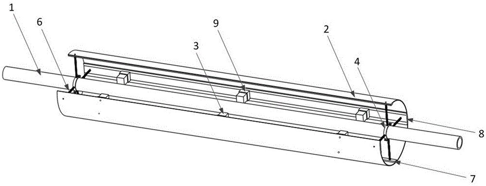
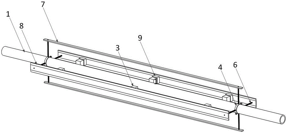
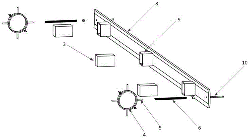
[0029] In actual use, the device of the present invention can be arranged at a certain interval as required. When the device of the present invention is installed, the oil pipeline 1 must first be transformed, and the pipeline to be transformed can be selected according to the root, and a layer of inner insulating layer 13 is added outside the steel pipe of the oil pipeline 1, and a layer of electrical conductor is arranged outside the inner insulating layer 13. Layer 12, and wires 11 are arranged outside the electrical conductor layer 12 to form a six-layer pipeline structure consisting of steel pipes, inner insulating layers 13, electrical conductor layers 12, wires 11, insulation layers and outer insulating layers from inside to outside, and make The wire 11 and the electrical conductor layer 12 form a closed electrical circuit. Then, install and fix the two support collars 4 on the oil pipeline 1 according to the interval between the openings at both ends of the correspond...


PUM


Abstract

The invention relates to a device and method for realizing undersea oil pipeline flow damping through vortex-induced vibration. The device is composed of a vibration system, a magnetic field system and an electrogenic heat tracing system. The vibration system is composed of an outer barrel, supporting plates, supporting lantern rings, springs and long bolts and is used for producing vibration responses under the ocean current action. The magnetic field system is composed of magnet clamping grooves and magnets and arranged on the wide supporting plate of the inner wall of the outer barrel and used for constructing a magnetic field. The electrogenic heat tracing system comprises wires, an electrical conductor layer and an inner insulation layer, and an oil pipeline is transformed to be of a six-layer pipeline structure which is composed of a steel pipe, the inner insulation layer, the electrical conductor layer, the wires, a heat preservation layer and an outer insulation layer from inside to outside in sequence. According to the device for realizing undersea oil pipeline flow damping through the vortex-induced vibration, the wires are driven by the vibration to cut magnetic induction lines under the ocean current action, and heat generated by electricity enables the viscosity and the resistance of an oil flow to be reduced, so that the low cost and zero energy consumption are achieved.

Description

technical field [0001] The invention belongs to the technical field of submarine pipeline fluid transportation, and in particular relates to a device and method for realizing flow drag reduction of a submarine oil pipeline by utilizing vortex-induced vibration. Background technique [0002] Due to the high viscosity and high energy consumption of heavy oil, the problem of flow drag reduction has always been a hot topic in the field of pipeline fluid transportation technology. With the continuous deepening of people's research on flow drag reduction, many heavy oil flow drag reduction methods have emerged, including hot water mixing, steam mixing, oil and gas mixed transportation, direct heating, electric heating, hot water heating, steam tracing, etc. Heat, water ring, foam injection, viscosity reducer injection, etc. Most of them have achieved good drag reduction effects in the application of surface oil pipelines, but at the same time, obvious defects have been exposed. ...

Claims


Application Information

Patent Timeline
Patent Type & Authority Applications(China)
IPC IPC(8): F16L53/00F03B13/00H02J7/32
CPCF03B13/00F16L53/34H02J7/32
Inventor 朱红钧孙兆鑫尤嘉慧姚杰唐有波廖梓行
Owner SOUTHWEST PETROLEUM UNIV
Why Eureka
Try Eureka