Combustion kiln system

A kiln chamber and control device technology, applied in the field of combustion kiln, can solve the problems of low combustion efficiency of the combustion kiln, achieve the effect of avoiding uncontrollable heating temperature and improving combustion efficiency

Inactive Publication Date: 2016-04-27
CHONGQING SHENGSHANGYUAN ENVIRONMENTAL GOVERNANCE CO LTD
View PDF5 Cites 0 Cited by
  • Summary
  • Abstract
  • Description
  • Claims
  • Application Information

AI Technical Summary

Problems solved by technology

[0002] At present, when using a combustion kiln to make ceramsite from sludge, the blank is directly put into the kiln. Because the heating temperature and heating time required for the ceramsite blank made from sludge are different in each stage of drying, puffing and sintering, the The overall heating of the combustion kiln may easily cause low combustion efficiency of the combustion kiln

Method used


Image

  • Combustion kiln system
  • Combustion kiln system

Examples


Embodiment 1

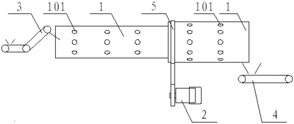
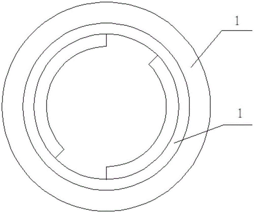
[0029] see Figure 1-2 , is a schematic structural diagram of the combustion kiln system provided by the present invention.

[0030] The present invention provides a combustion kiln system, comprising: a plurality of combustion kiln chambers 1 connected end-to-end in sequence, the inlets and outlets of adjacent combustion kiln chambers 1 are connected; a driving device 2 for driving a plurality of combustion kiln chambers 1 to rotate; and The drive device 2 is electrically connected to the control device, the control device can adjust the rotating speed of the drive device 2; the combustion kiln chamber 1 is provided with a temperature detection point for detecting the internal temperature of the combustion kiln chamber 1, the temperature detection device is electrically connected to the control device, and the temperature detection device The detected temperature signal can be transmitted to the control device, and the control device controls the size of the feed amount accor...

Embodiment 2

[0034] In yet another embodiment provided by the present invention, the structure of the combustion kiln system in this embodiment is similar to that in Embodiment 1, and the similarities will not be repeated, and only the differences will be introduced.

[0035] In this embodiment, the present invention discloses that the combustion kiln system also includes a feed device 3; The device is electrically connected, and the control device can control the feeding amount of the feeding device 3 by controlling the rotating speed of the power device, thereby reducing the intensity of manual operation. Specifically, the present invention discloses that the feeding device 3 is a conveyor belt device.

[0036] In order to further reduce the labor intensity and improve the degree of automation, the present invention also discloses that the combustion kiln system also includes a discharge device 4; the discharge device 4 is used to receive the materials output from the discharge port of t...


PUM


Abstract

The invention discloses a combustion kiln system. The combustion kiln system comprises a plurality of combustion kiln chambers sequentially communicated end to end, a drive device for driving combustion kilns of the combustion kiln system to rotate, a control device electrically connected to the combustion kiln system drive device, a temperature detecting device, and a heating device, wherein control device for the combustion kiln system can regulate rotation speed of the combustion kiln system drive device; the temperature detecting device is used for determining the temperature of the inner parts of the combustion kiln chambers; the temperature detecting device for the combustion kiln system is electrically connected to the control device for the combustion kiln system; and the heating device is used for heating each combustion kiln of the combustion kiln system. In use, the control device controls the drive device to drive the combustion kilns to rotate so as to control the rotation speed, and the combustion kiln system comprises the plurality of the combustion kiln chambers, and therefore, the plurality of the combustion kiln chambers can be respectively heated, difference of the inner temperatures of the plurality of the combustion kiln chambers and retention time of blank is realized, different temperature needs, at each stage, of the blank are met, sectional heating effect is realized, and the combustion efficiency of the combustion kiln system is improved.

Description

technical field [0001] The invention relates to the technical field of combustion kilns, in particular to a combustion kiln system. Background technique [0002] At present, when using a combustion kiln to make ceramsite from sludge, the blank is directly put into the kiln. Because the heating temperature and heating time required for the ceramsite blank made from sludge are different in each stage of drying, puffing and sintering, the The overall heating of the combustion kiln is likely to cause low combustion efficiency of the combustion kiln. [0003] Therefore, how to improve the combustion efficiency of sludge-made ceramsite combustion kiln is a technical problem to be solved urgently by those skilled in the art. Contents of the invention [0004] In view of this, the object of the present invention is to provide a combustion kiln system, which can improve the combustion efficiency of the combustion kiln for ceramsite made from sludge. [0005] In order to achieve t...

Claims


Application Information

Patent Timeline
Patent Type & Authority Applications(China)
IPC IPC(8): F27B13/02F27B13/06F27B13/12F27B13/14
CPCF27B13/02F27B13/06F27B13/12F27B13/14F27M2001/10
Inventor 胡犇胡万军
Owner CHONGQING SHENGSHANGYUAN ENVIRONMENTAL GOVERNANCE CO LTD
Why Eureka
Try Eureka