Embedded air conditioning inner unit and shell thereof

A technology for embedded air conditioners and internal units, which is applied in air conditioning systems, heating methods, space heating and ventilation, etc. It can solve the problems of easy discoloration in the air inlet area, small area, and monotonous overall surface appearance, and achieve convenient positioning and installation. The effect of stable placement, improving heat exchange efficiency, and increasing lighting effects

Active Publication Date: 2016-05-04
QINGDAO HAIER AIR CONDITIONING ELECTRONICS CO LTD
View PDF8 Cites 3 Cited by
  • Summary
  • Abstract
  • Description
  • Claims
  • Application Information

AI Technical Summary

Problems solved by technology

from figure 1 It can be seen that the traditional embedded air conditioner has a simple appearance, monotonous surface technology, complicated production, and needs to be hoisted behind the ceiling, which makes installation and after-sales maintenance difficult
The air outlet 101 and the air inlet 102 are on the same plane, so the heat exchange efficiency is low
The air inlet 102 is on the front panel. After the user uses it for a long time, it is easy to stick dust near the air inlet 102, and the air inlet area is easy to change color, affecting the appearance
In addition, because the air outlet 101 and the air inlet 102 of the traditional embedded machine are on the same plane, the area for the design of the front panel is small, and only ordinary injection molding can be used at present. The panel frame is square, and the overall surface appearance is monotonous
The production and installation are more complicated. The front panel and the machine body are separated into two parts, which need to be reassembled at the user's home.
The traditional hoisting part is on the side of the machine body, the panel frame area is larger than the periphery of the machine body, and the machine body is hidden behind the ceiling, which is inconvenient for construction

Method used


Image

  • Embedded air conditioning inner unit and shell thereof
  • Embedded air conditioning inner unit and shell thereof
  • Embedded air conditioning inner unit and shell thereof

Examples


Embodiment Construction

[0042] In order to make the object, technical solution and advantages of the present invention clearer, the present invention will be further described in detail below in conjunction with the accompanying drawings and embodiments. It should be understood that the specific embodiments described here are only used to explain the present invention, not to limit the present invention.

[0043]The inner surface and outer surface described in the embodiments of the present invention are based on the shell of the embedded air conditioner inner unit. The surface facing the inside of the housing is the inner surface (even if it is exposed outside the closed area of ​​the housing, as long as the surface extending towards the inside of the housing is also an inner surface), the surface facing the outside of the housing is the outer surface.

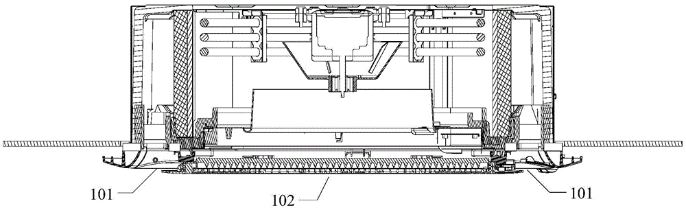
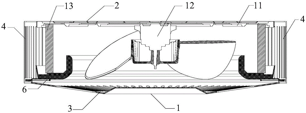
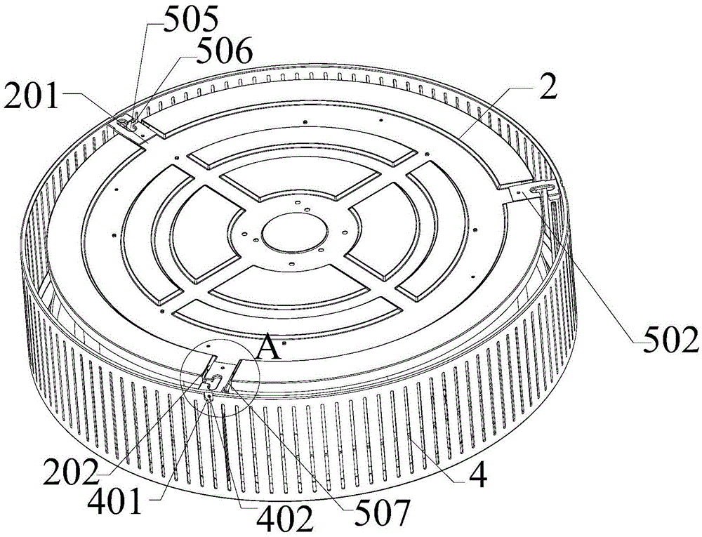
[0044] An embodiment of the present invention provides a casing of an embedded air conditioner inner unit. Such as Figure 2-8 As shown, they are...


PUM


Abstract

The invention discloses a shell of an embedded air conditioning inner unit. The shell comprises a first panel, a second panel, an air outlet grid, a first air inlet grid and multiple connecting rods; the first panel and the second panel are parallel to each other; an air outlet is formed in the first panel; the air outlet grid is arranged in the air outlet; the first air inlet grid is arranged between the first panel and the second panel, and surrounds as a whole with the first panel and the second panel; a first connecting plate and a second connecting plate are arranged at one ends of the connecting rods; one end of the first connecting plate is connected with one end of the second connecting plate; an included angle is formed between the first connecting plate and the second connecting plate; the second connecting plate is parallel to the second panel; one side of the first air inlet grid is fixedly connected with the first connecting plate; and the second connecting plate is joined on the outer surface of the second panel. The invention further discloses the embedded air conditioning inner unit. The embedded air conditioning inner unit and the shell improve the heat exchange efficiency.

Description

technical field [0001] The invention relates to the field of air conditioners, in particular to an embedded air conditioner inner unit and its shell. Background technique [0002] Such as figure 1 As shown in FIG. 1 , it is a structural schematic diagram of an air conditioner internal unit in the prior art. from figure 1 It can be seen that the traditional embedded air conditioner has a simple appearance, monotonous surface technology, complicated production, and needs to be hoisted behind the ceiling, making installation and after-sales maintenance difficult. The air outlet 101 and the air inlet 102 are on the same plane, so the heat exchange efficiency is low. The air inlet 102 is on the front panel. After the user uses it for a long time, it is easy to stick dust near the air inlet 102, and the air inlet area is easy to change color, which affects the appearance. In addition, because the air outlet 101 and the air inlet 102 of the traditional embedded machine are on t...

Claims


Application Information

Patent Timeline
Patent Type & Authority Applications(China)
IPC IPC(8): F24F1/00F24F13/20F24F13/08
CPCF24F1/0007F24F13/082F24F13/20
Inventor 张吉义陈冬铃李冬梅董德智
Owner QINGDAO HAIER AIR CONDITIONING ELECTRONICS CO LTD
Why Eureka
Try Eureka