Photoelectric aiming system look-down tracking test method and test device for implementing the method

A photoelectric aiming and testing device technology, applied in the direction of guidance, weapon accessories, offensive equipment, etc., can solve the problems of test blind spots, photoelectric aiming system unable to observe the collimator cursor, and unable to keep target tracking, etc., to achieve increased test , increase the range, and ensure a sufficient degree of effect

Active Publication Date: 2018-02-13
LUOYANG INST OF ELECTRO OPTICAL EQUIP OF AVIC
View PDF4 Cites 0 Cited by
  • Summary
  • Abstract
  • Description
  • Claims
  • Application Information

AI Technical Summary

Problems solved by technology

However, when it is necessary to use the cursor of the collimator to simulate the target directly below the photoelectric sighting system, the receiving end of the photoelectric sighting system will face vertically downward. The cursor of the collimator cannot be observed, so the existing test device can only realize the tracking performance test within a limited pitch range. The occlusion of the target cannot keep track of the target, and there is a blind spot in the test

Method used


Image

  • Photoelectric aiming system look-down tracking test method and test device for implementing the method
  • Photoelectric aiming system look-down tracking test method and test device for implementing the method
  • Photoelectric aiming system look-down tracking test method and test device for implementing the method

Examples


Embodiment Construction

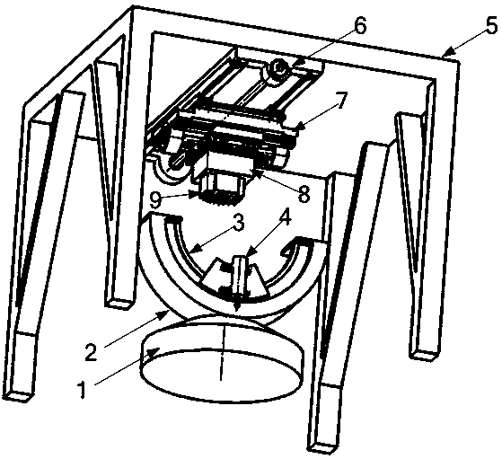
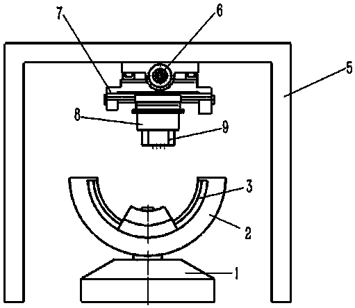
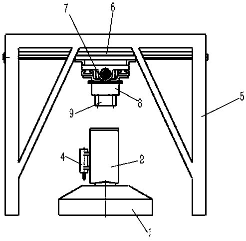
[0027] The embodiment of testing device among the present invention: as Figure 1 to Figure 4 As shown, the test device is a multi-frame decoupling downward-looking tracking test system in the technical field of airborne photoelectric sighting system control performance testing. It is mainly composed of a two-dimensional horizontal turntable and a hoisting base. A collimator is installed, and the hoisting base is used to install the photoelectric aiming system to be tested above the collimator.

[0028] The two-dimensional horizontal turntable includes a turntable base 1 and an azimuth frame 2 mounted on it that rotates around a vertically extending axis. Between the azimuth frame 2 and the collimator 4 is a device for driving the collimator 4 along the upper edge of the azimuth frame 2. A traverse mechanism that moves vertically in the direction of the rotation axis of the azimuth frame 2. The traverse mechanism includes a traverse guide rail 3 fixed on the azimuth frame 2 an...


PUM


Abstract

The invention discloses a photoelectric aiming system look-down tracking test method and a test device for implementing the method. The test device includes a two-dimensional turntable, a collimator is mounted on the two-dimensional turntable, and an installation part for fixing the position of the photoelectric aiming system is arranged above the collimator, and the installation part is assembled on the frame. The invention realizes the relative movement between the collimator and the photoelectric aiming system by driving the collimator to move with a two-dimensional turntable, thereby simulating the movement of the radio and television aiming system relative to the target source. During this process, the parallel light emitted by the collimator The light source is always facing upwards, so that the photoelectric sighting system above the collimator will not have a blind spot in the field of view. Especially when it is necessary to test the downward viewing performance of the photoelectric sighting system for the target directly below, the photoelectric sighting system can be placed directly on the collimator. At this time, the collimator and the photoelectric sighting system will not be interfered by the two-dimensional turntable, thus increasing the scope of the photoelectric sighting system's downward-looking tracking performance test.

Description

technical field [0001] The invention relates to a photoelectric aiming system look-down tracking test method and a test device for implementing the method. Background technique [0002] At present, after combat aircraft such as transport planes, bombers, drones, and helicopters launch laser-guided weapons, the airborne photoelectric targeting system needs to keep track of the target and provide irradiation guidance for laser-guided weapons. Since most laser-guided weapons have no power, and the flying speed of the weapons is lower than that of the carrier aircraft after delivery, there is often a need for the photoelectric targeting system to look down and track the target. In this way, when testing the tracking performance of the photoelectric sighting system, it is necessary to test the down-looking tracking performance of the photoelectric sighting system. The downward-looking tracking performance test process of the existing photoelectric sighting system is as follows: ...

Claims


Application Information

Patent Timeline
Patent Type & Authority Patents(China)
IPC IPC(8): F41G3/32F41G3/22
CPCF41G3/22F41G3/32
Inventor 孔卫国窦光继罗永胜黄庆冯长远王合龙
Owner LUOYANG INST OF ELECTRO OPTICAL EQUIP OF AVIC
Why Eureka
Try Eureka