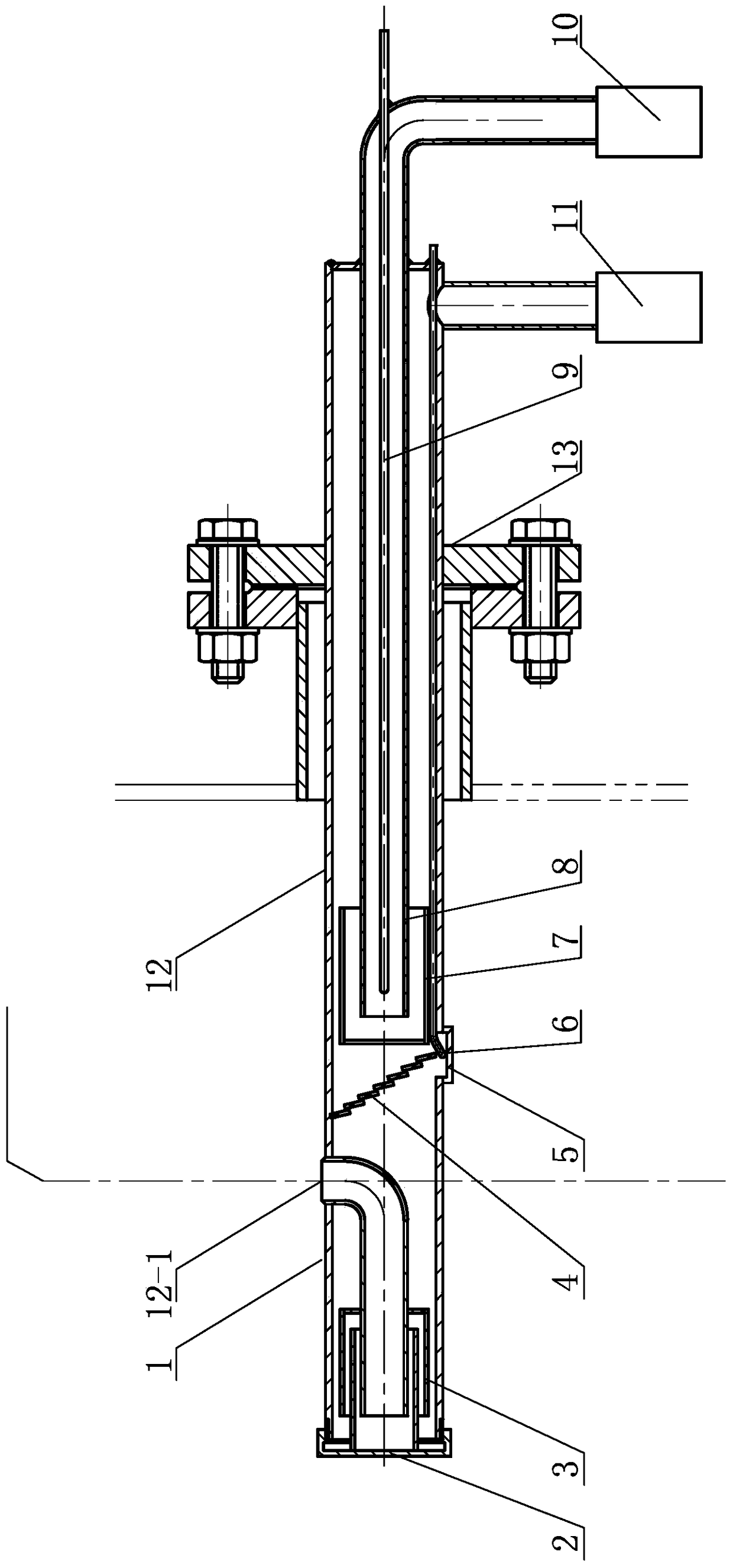
A low-temperature and high-humidity exhaust gas temperature measurement and sampling device for condensing gas-fired boilers
A gas-fired boiler, low temperature and high humidity technology, used in measuring devices, sampling devices, temperature measurement of moving fluids, etc., can solve the problems of accelerating the flow rate of flue gas, unable to ensure the synchronization of temperature measurement of droplets, etc., and achieve reliable work and sufficient separation. Effect
- Summary
- Abstract
- Description
- Claims
- Application Information
AI Technical Summary
Problems solved by technology
Method used
Image
Examples
specific Embodiment approach 1
[0011] Specific implementation mode one: combine figure 1 To illustrate this embodiment, a low-temperature, high-humidity exhaust gas temperature measurement and sampling device for a condensing gas-fired boiler in this embodiment includes a wet gas suction pump 11, a sampling gun sleeve 12, a reverse flow air intake mechanism, a condensed water The temperature measurement mechanism and the clean flue gas sampling mechanism, the sampling gun casing 12 is set horizontally, the right end of the sampling gun casing 12 is connected to the wet flue gas suction pump 11, the reverse flow air intake mechanism, the condensed water temperature measurement The mechanism and the clean flue gas sampling mechanism are sequentially arranged in the sampling gun casing 12 from left to right.
[0012] In this embodiment, the inlet of wet flue gas is arranged in the center of the flue of the condensing gas boiler.
specific Embodiment approach 2
[0013] Specific implementation mode two: combination figure 1 Describe this embodiment. The reverse flow intake mechanism of a low-temperature, high-humidity exhaust gas temperature measurement and sampling device for a condensing gas-fired boiler in this embodiment includes a reverse flow intake pipe 1, a baffle plate 2, and a back-type reflux cover 3. The baffle plate 2 is installed at the left end port of the sampling gun casing 12, and the return type reflux cover 3 and the reverse flow air intake pipe 1 are arranged in the left end of the sampling gun casing 12 from left to right in sequence, and the reverse flow enters the The left end of the trachea 1 is inserted into the return type reflux hood 3, and the right end of the reverse flow air inlet pipe 1 is connected with the reverse flow air inlet 12-1 on the outer wall of the sampling gun sleeve 12. The wet smoke flows through the reverse intake pipe 1 to form a high-speed jet impacting the baffle 2, and the baffle 2 an...
specific Embodiment approach 3
[0014] Specific implementation mode three: combination figure 1 Describe this embodiment. The condensate temperature measurement mechanism of a low-temperature, high-humidity exhaust gas temperature measurement and sampling device for a condensing gas-fired boiler in this embodiment includes a mesh corrugated plate separator 4, a droplet collection tray 5 and a condensate temperature measurement mechanism. As for the measuring device 6 , the droplet collecting tray 5 is arranged under the mesh corrugated plate separator 4 , and the measuring end of the condensed water temperature measuring device 6 is arranged in the droplet collecting tray 5 . The mesh corrugated plate separator 4 catches the fine liquid droplets in the airflow, and collects the liquid droplets in the condensed water collection pan 5 in a direction, and the condensed water collection pan 5 collects the liquid droplets separated from the gas-liquid separation section of the sampling gun, and at the same time o...
PUM
 Abstract
Description
Claims
Application Information
 - R&D
- Intellectual Property
- Life Sciences
- Materials
- Tech Scout
- Unparalleled Data Quality
- Higher Quality Content
- 60% Fewer Hallucinations
Browse by: Latest US Patents, China's latest patents, Technical Efficacy Thesaurus, Application Domain, Technology Topic, Popular Technical Reports.
© 2025 PatSnap. All rights reserved.Legal|Privacy policy|Modern Slavery Act Transparency Statement|Sitemap|About US| Contact US: help@patsnap.com

