
Automatic rotary-disc type fluorescence detector

A detector and turntable technology, which is applied in the field of automatic turntable fluorescence detector, can solve the problems of reduced detection efficiency, measurement result error, waste of manpower and material resources of fluorescence detector, etc., to speed up detection, improve accuracy, and save manpower Material effect

Active Publication Date: 2016-05-04
王治才
View PDF7 Cites 33 Cited by
  • Summary
  • Abstract
  • Description
  • Claims
  • Application Information

AI Technical Summary

Problems solved by technology

[0003] In view of the above problems, the purpose of the present invention is to provide an automatic turntable fluorescence detector, which solves the waste of manpower and material resources caused by the need to put reagent cards one by one into the related fluorescence detectors, the detection efficiency is reduced, and the technical problems that the measurement results are easy to cause errors

Method used


Image

  • Automatic rotary-disc type fluorescence detector
  • Automatic rotary-disc type fluorescence detector
  • Automatic rotary-disc type fluorescence detector

Examples


Embodiment 1

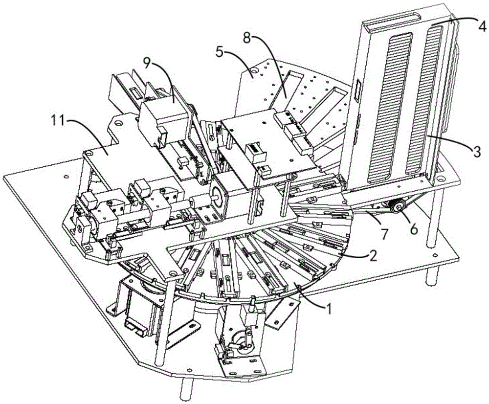
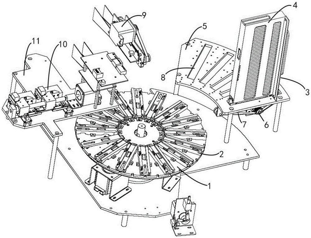
[0031] The automatic turntable fluorescence detector includes a reagent card conveying device, a card reading and detecting device 10, an automatic card dropping device 9 and an automatic card feeding device 3 adjacent to the reagent card conveying device.

[0032] In this embodiment, the reagent card delivery device is a reagent card carrier tray.

[0033] like figure 1 and figure 2 As shown, the surface of the reagent card carrier tray 1 is provided with a plurality of reagent card holders 2 at intervals along the circumferential direction, and the reagent card holders 2 extend radially to the outer circumference of the reagent card carrier tray 1 to facilitate reagent card The outward opening of the fixing member 2 is docked with the automatic card feeding device 3 to avoid collision when receiving the reagent card 31 to be tested.

[0034] The card reading detection device 10 includes a test light path box for detecting the fluorescence intensity of the reagent card 31 ...

Embodiment 2

[0042] In this embodiment, the reagent card fixing part is a dial chuck with a plurality of compartments whose width is suitable for the width of the reagent card evenly spaced along the circumference, and the compartments extend radially to the outer circumference, and the The compartment forms a card slot for placing reagent cards on the reagent card carrier tray. The dial chuck is superimposed on the reagent card carrier plate, and the reagent card carrier plate is fixed, and the dial chuck rotates relative to the reagent card carrier plate.

Embodiment 3

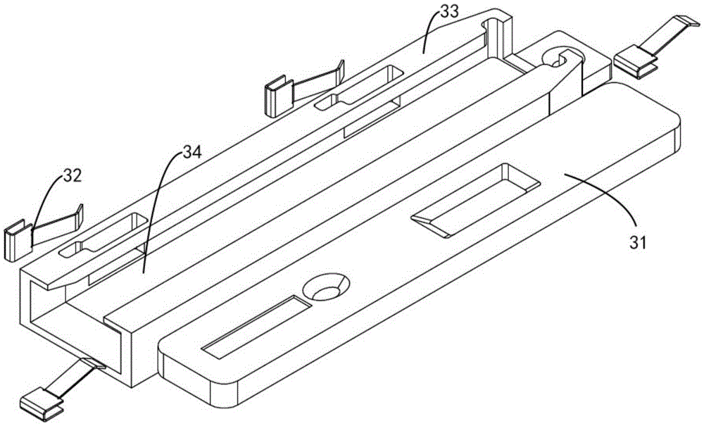
[0044] In order to avoid errors in the test results due to the gap between the reagent card 31 and the groove 34, the card reading detection device 10 and the automatic card dropping device 9 can be integrated, and the reagent card 31 can be taken out from the groove 34 before performing the test. detection.

[0045] In this example, if Figure 5 As shown, the automatic card dropping device 9 is arranged on one side of the reagent card carrier tray 1 . The automatic card dropping device 9 includes a card dropping slide plate 55 , a blocking card 56 , a loading tab 57 for loading reagent cards, and a moving guide rail 58 for driving the loading tab 57 . The measuring optical path box 53 is arranged on the same straight line as the blocking card 56 and the mounting tab 57 . After the reagent card in the reagent card fixing part enters the loading tab 57 , the loading tab 57 passes through the measuring light path box 53 and the blocking card 56 sequentially under the drive of ...


PUM


Abstract

The invention relates to an automatic rotary-disc type fluorescence detector. The fluorescence detector comprises a reagent card conveyer, a card reading and detecting device, an automatic card falling device, and an automatic card feeding device adjacent to the reagent card conveyer. Reagent card fixing parts are arranged on the surface of the reagent card conveyer to receive reagent cards input by the automatic card feeding device. The card reading and detecting device comprises a testing light path box for detecting fluorescence strength of the reagent cards and a bar code recognizer for recognizing bar code information. The automatic card feeding device comprises a pushing structure which pushes the reagent cards to enter the reagent card fixing parts. According to the automatic rotary-disc type fluorescence detector, by arranging the automatic card falling device and the automatic card feeding device, the objective of automatic batch detection of the reagent cards to be detected is achieve, and detectors need not place in the reagent cards to be detected one by one, so that lots of manpower and material resources are saved, and detection efficiency and accuracy of detected results are improved.

Description

technical field [0001] The invention relates to the field of medical detection instruments, in particular to an automatic turntable fluorescence detector. Background technique [0002] Dry fluorescent detection technology is a rapid medical detection technology that uses dry fluorescent reagent cards as the carrier and is used in combination with the measurement optical path, barcode reader and test platform. Reaction to form a conjugate, which emits a specific spectrum of emission fluorescence under the excitation of a specific wavelength of excitation light. The emission light is proportional to the analyte. By testing the fluorescence intensity of the emission light, the analyte can be qualitatively tested or quantitative analysis. The existing dry-type fluorescence detector is mainly composed of a measuring light path and a test platform for placing dry-type fluorescent reagent cards. The tester needs to put the reagent cards to be tested into the test platform one by o...

Claims


Application Information

Patent Timeline
Patent Type & Authority Applications(China)
IPC IPC(8): G01N21/64G01N35/02G01N35/04
CPCG01N21/6428G01N35/025G01N35/04G01N2035/00356G01N2035/00455G01N2035/0443
Inventor 王治才张平李军民王平美
Owner 王治才
Learn More