
LTCC filter testing board and testing clamping tool

A technology of test fixtures and test boards, which is applied in the direction of instruments, measuring electronics, and measuring devices, can solve the problems of large test errors and large test errors of test fixtures, and achieve the effect of small test loss and good stability

Active Publication Date: 2016-05-04
SHENZHEN ZHENHUA FU ELECTRONICS +1
View PDF6 Cites 10 Cited by
  • Summary
  • Abstract
  • Description
  • Claims
  • Application Information

AI Technical Summary

Problems solved by technology

[0003] In the traditional DC-6GHz frequency band product test, the test fixture used has a large test error, especially the product test error of the test frequency band above 1GHz is even greater

Method used


Image

  • LTCC filter testing board and testing clamping tool
  • LTCC filter testing board and testing clamping tool
  • LTCC filter testing board and testing clamping tool

Examples


Embodiment Construction

[0025] In order to make the object, technical solution and advantages of the present invention clearer, the present invention will be further described in detail below in conjunction with the accompanying drawings and embodiments. It should be understood that the specific embodiments described here are only used to explain the present invention, not to limit the present invention.

[0026] An LTCC filter test board is used in the LTCC filter test process to realize the test function of the S parameter of the LTCC filter. S parameters are also called scattering parameters, including through S parameters and reflection S parameters. The straight-through S parameters include the reverse transmission coefficient S12 and the forward transmission coefficient S21. Thru S-parameters are used to reflect the insertion loss of a device. Reflection S parameters include input reflection system S11 and output reflection coefficient S22, which are used to characterize the return loss of th...


PUM


Abstract

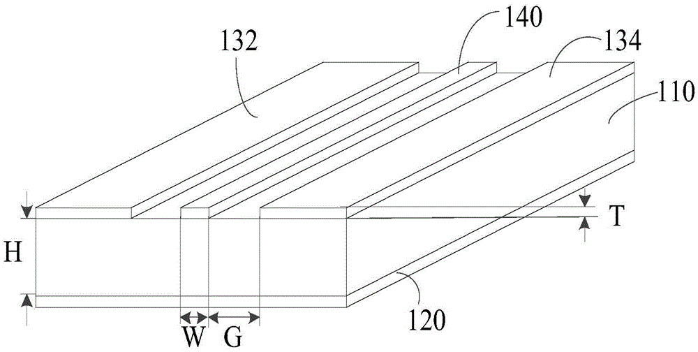
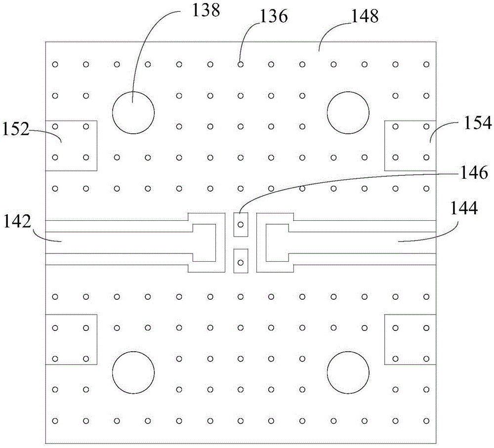
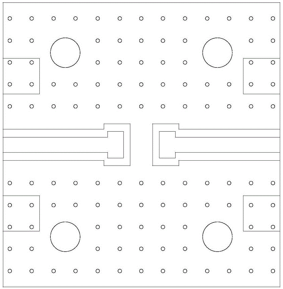
The invention discloses an LTCC filter testing board, and the testing board comprises a substrate, a first grounding layer, a second grounding layer, a third grounding layer, and a signal transmission layer. The first grounding layer is disposed on a first surface of the substrate, and the second and third grounding layers and the signal transmission layer are disposed on a second surface of the substrate in a mutually insulated manner, thereby forming a coplanar waveguide structure. The second and third grounding layers are respectively in electrical connection with the first grounding layer through a grounding layer connection hole. Two ends of each of the second and third grounding layers are respectively connected with a negative input end and a negative output end. Two ends of the signal transmission layer are respectively provided with a signal input end and a signal output end. Parts, located at centers of the signal input and output ends, of the signal transmission layer are provided with binding pads. The bonding pads are electrically connected with a to-be-measured LTCC filter. The testing error of the testing board is small, and the testing frequency range is larger. The invention also relates to an LTCC filter testing clamping tool.

Description

technical field [0001] The invention relates to the technical field of electronic device testing, in particular to an LTCC filter testing board and a testing fixture. Background technique [0002] LTCC (LowTemperatureCo-firedCeramic, low temperature co-fired ceramic) filter is a frequency-selective device suitable for microwave frequency bands, and is widely used in microwave communications, radar navigation, satellite communications, and automotive electronics. In recent years, with the development requirements of high integration and miniaturization of the whole machine system, LTCC filters have been widely used due to their small size, good electrical consistency in the microwave frequency band, and high reliability. The LTCC filter is a monolithic structure electronic component prepared by low temperature co-firing technology (the frequency band used covers DC-40GHz), and its common terminal electrodes are 4, 6, 8, 10, etc., including three types of terminal electrodes: ...

Claims


Application Information

Patent Timeline
IPC IPC(8): G01R31/00G01R1/04
CPCG01R1/0425G01R31/00
Inventor 罗洪梁林亚梅黄寒寒刘季超朱建华胡志明
Owner SHENZHEN ZHENHUA FU ELECTRONICS
Learn More