

Bottom-debugging cavity filter
A filter and cavity technology, which is applied in the field of filters, can solve problems such as complicated maintenance and replacement of equipment, poor outlet threaded holes, poor quality control, etc., and achieve the effects of improved debugging effect, low replacement cost, and good debugging effect
- Summary
- Abstract
- Description
- Claims
- Application Information
AI Technical Summary
Problems solved by technology
Method used
Image

Examples
specific Embodiment 1
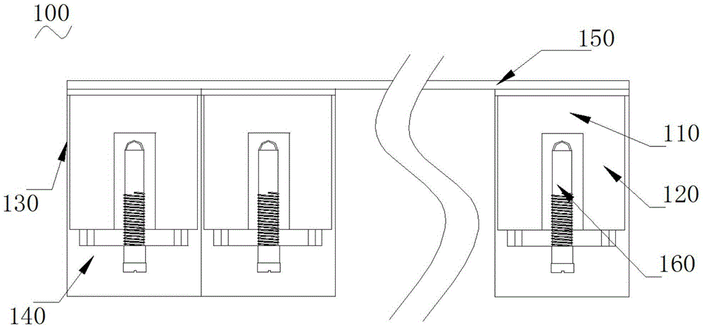
[0035] Such as figure 1 Shown is a structural schematic diagram of a specific embodiment 1 of the present invention.
[0036] The bottom debugging cavity filter 100 includes one or more cavities 110, an inner conductor 120 located inside the cavity 110 for conducting electricity, an outer conductor 130 located outside the cavity 110 for conducting electricity, and the outer conductor 130 and the inner conductor 130 The base 140 to which the conductors 120 are electrically connected, the housing cover 150 covering the top of all cavities 110 , and the tuning element 160 located at the bottom of each cavity 110 for debugging.
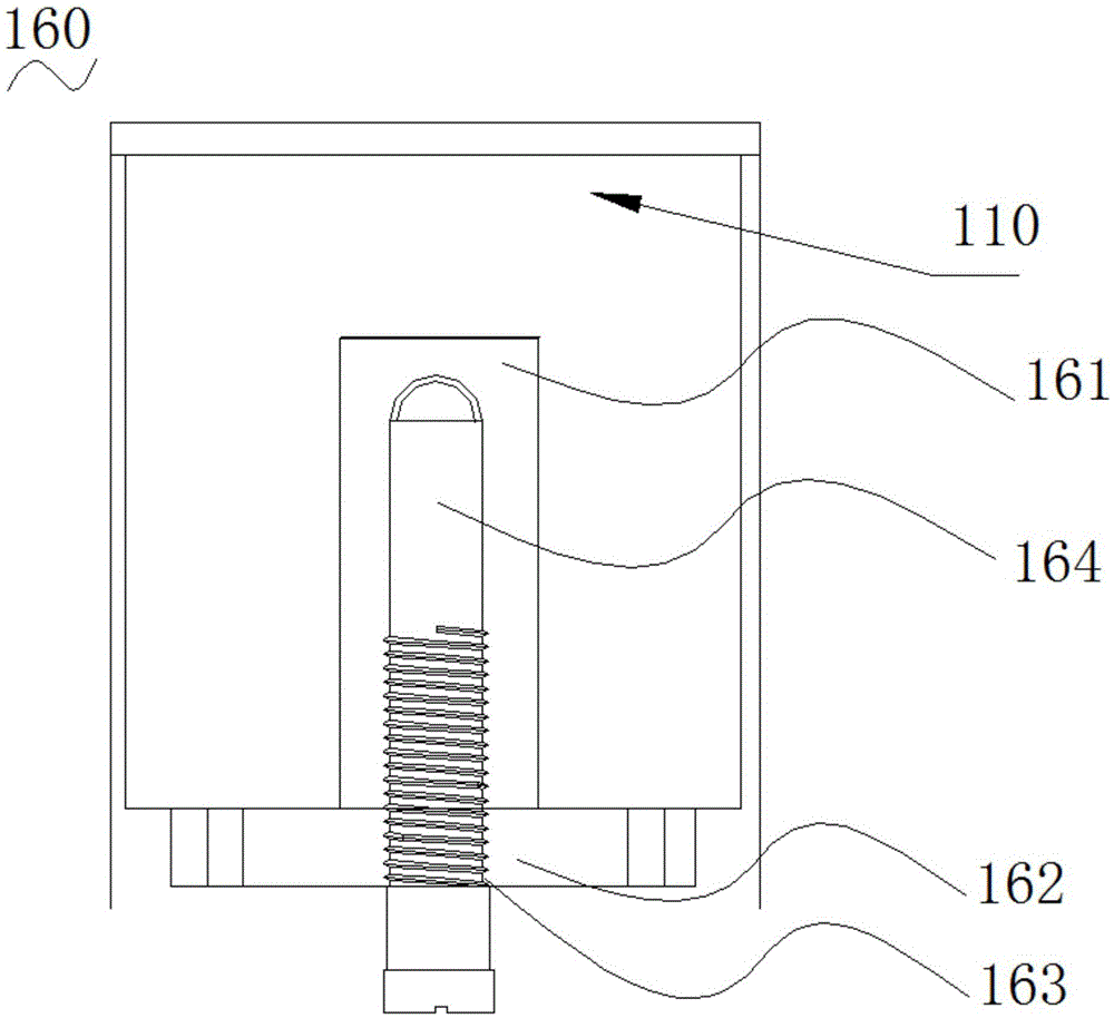
[0037] Such as figure 2 Shown is a schematic structural diagram of the tuning element in Embodiment 1 of the present invention.
[0038] The tuning element 160 includes a resonant column 161 installed at the bottom of the cavity 110, a small cover plate 162 covering the bottom of the cavity 110, a threaded hole 163 opened along the thickness direction ...
specific Embodiment 2
[0052] Such as Figure 6 As shown, it is a structural schematic diagram of the tuning screw of the second embodiment of the present invention.
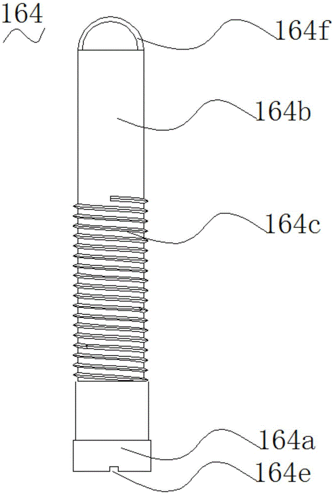
[0053] In this embodiment, the structure and working principle of the bottom-tuned cavity filter 100 are the same as those in the first embodiment, the difference is that in this embodiment, the tuning screw 164 includes a screw head 164g and a screw head 164g connected to the screw The main body 164b of the head 164g, one end of the main body 164b is sleeved in the screw head 164g, and the axes of the two coincide. One is made of metal, and the other is made of non-metal, such as plastic. The screw head 164g and the main body 164b use two different materials to form a composite tuning screw 164, which combines the dual advantages of metal and plastic, so that the screw head 164g and the main body 164b have different temperature expansion coefficients, and the two can compensate each other Influenced by temperature changes, when the...
specific Embodiment 3
[0054] Such as Figure 7 Shown is a schematic structural diagram of the tuning screw of the third embodiment of the present invention.
[0055] In this embodiment, the structure and working principle of the bottom-tuned cavity filter 100 are the same as those in the first embodiment, the difference is that in this embodiment, the tuning screw 164 includes a screw head 164g and a screw head 164g connected to the screw The main body 164b of the head 164g, one end of the screw head 164g is sleeved in the main body 164b, and the axes of the two coincide, the outer wall of the main body 164b is provided with an external thread 164d, and one of the screw head 164g and the main body 164b is One is made of metal, and the other is made of non-metal, such as plastic. The screw head 164g and the main body 164b use two different materials to form a composite tuning screw 164, which combines the dual advantages of metal and plastic, so that the screw head 164g and the main body 164b have ...
PUM
 Abstract
Description
Claims
Application Information