Energy-saving and efficient motor housing with high positioning accuracy

A technology of positioning accuracy and motor casing, applied in the direction of casing/cover/support, electrical components, electromechanical devices, etc., can solve the problems of reduced positioning accuracy, difficulty, accumulation of positioning deviation, etc., to reduce manufacturing costs and reduce materials Dosage, the effect of improving positioning accuracy

Inactive Publication Date: 2016-05-04
JIANGSU KIND ELECTRIC CO LTD
View PDF5 Cites 4 Cited by
  • Summary
  • Abstract
  • Description
  • Claims
  • Application Information

AI Technical Summary

Problems solved by technology

[0003] It can be seen that when the positioning plate is welded to the upper shell, there is a positioning deviation, and when the positioning mark is positioned and connected with other external parts of the motor shell, there is another positioning deviation, which will cause the accumulation of positioning deviations. There is a certain influence on the positioning of the motor housing and other external components, resulting in a decrease in positioning accuracy and an imprecise assembly structure.
This unfavorable factor will highlight its negative impact on product quality in products such as electric dampers that are small in size but have many transmission parts and transmission mechanisms.
Either have high requirements for assemblers and assembly machines, or have high requirements for the manufacturing precision of parts, so as to minimize deviations, but for small parts, these methods are obviously more difficult
[0004] The pawls on the upper case and the lower case, if attached figure 2 As shown, it is formed by radial punching from the side wall surface starting from the center of the circle. After punching, the scattered excess material generated on the side wall surface needs to be removed, and it is waste material, which has a large waste and is not conducive to cost control.

Method used


Image

  • Energy-saving and efficient motor housing with high positioning accuracy
  • Energy-saving and efficient motor housing with high positioning accuracy
  • Energy-saving and efficient motor housing with high positioning accuracy

Examples


Embodiment Construction

[0015] Below in conjunction with accompanying drawing and specific embodiment, further illustrate the present invention, should be understood that these embodiments are only for illustrating the present invention and are not intended to limit the scope of the present invention, after having read the present invention, those skilled in the art will understand various aspects of the present invention Modifications in equivalent forms all fall within the scope defined by the appended claims of this application.

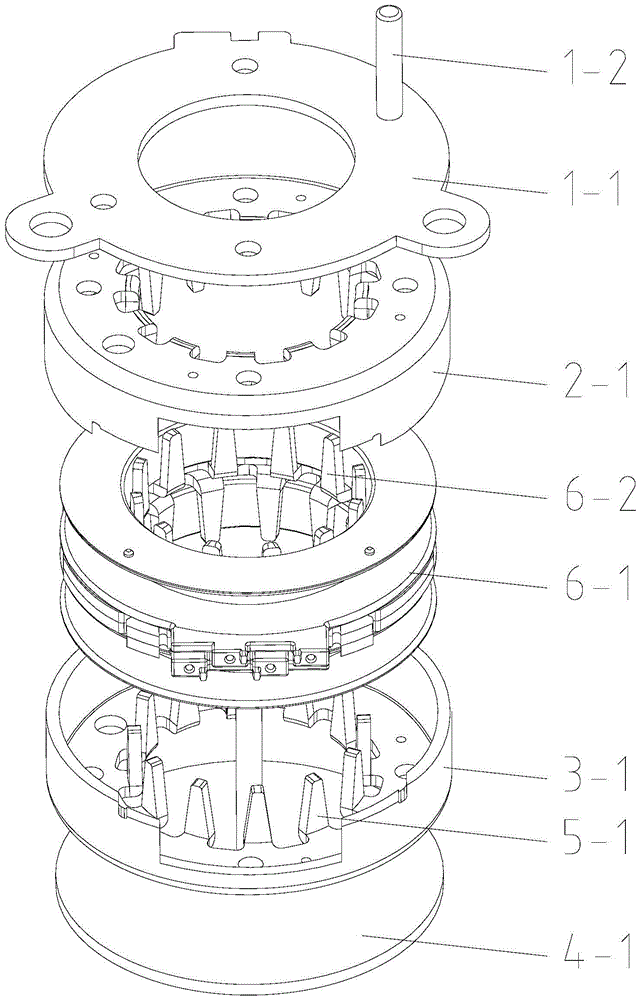
[0016] An energy-saving, high-efficiency, and high-precision motor casing is composed of an upper casing and a lower casing.

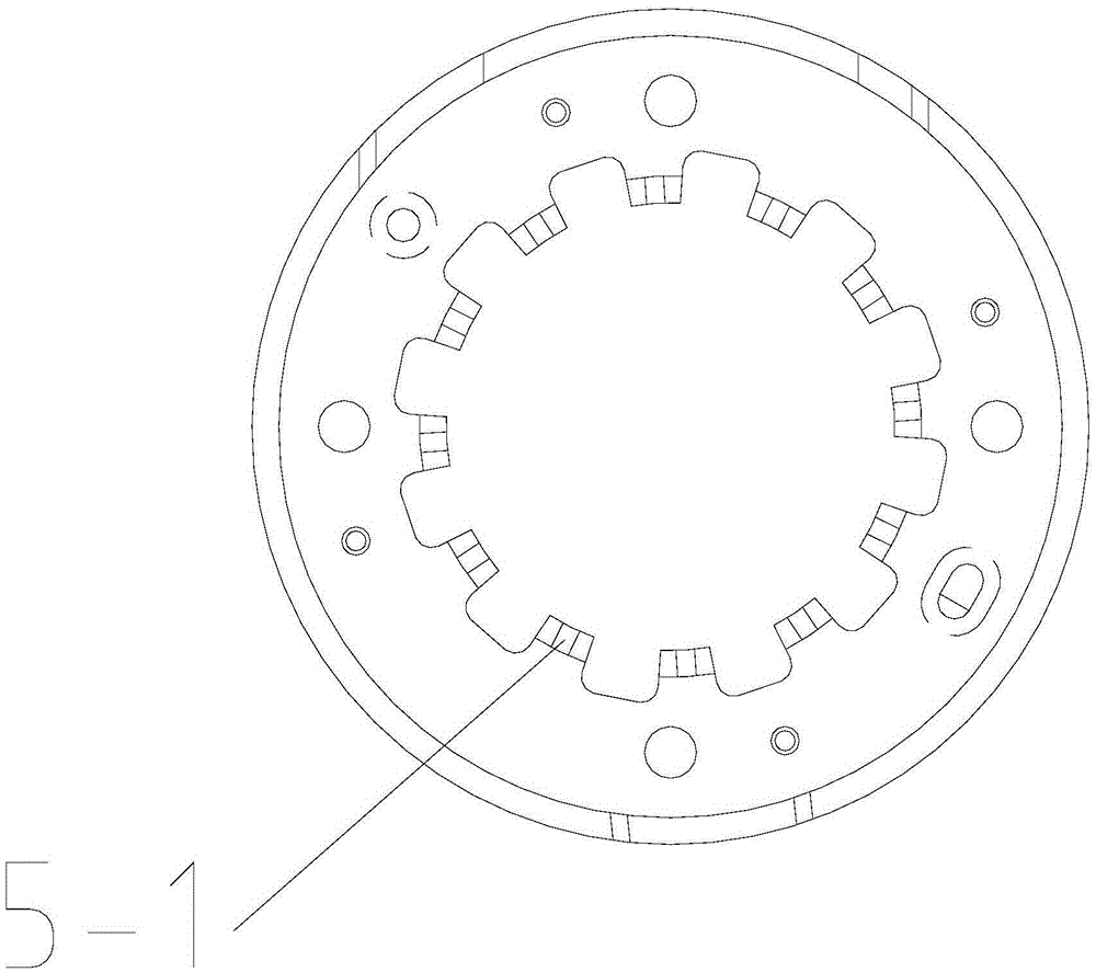
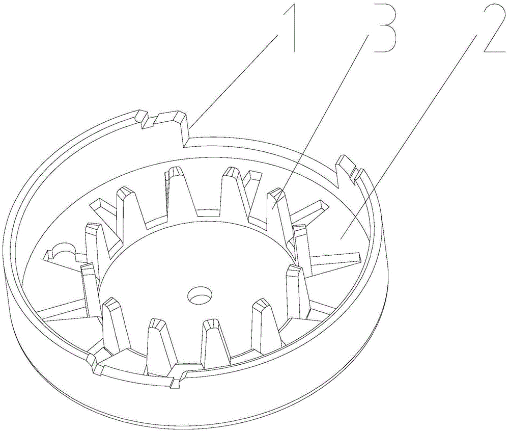
[0017] as attached image 3 , 4 As shown, there is a positioning mark 1 on the upper shell and / or the lower shell, and the positioning mark can be in the form of a positioning column, a positioning hole, a positioning bayonet, etc., and the inner sides of the side walls 2 of the upper shell and the lower shell have pawls 3 .

[0018] Determine...


PUM


Abstract

The invention discloses an energy-saving and efficient motor housing with high positioning accuracy. The motor housing comprises an upper shell and a lower shell, wherein positioning marks are arranged on the upper shell and / or the lower shell; pawls are arranged at the inner sides of the side wall surfaces of the upper shell and the lower shell and are punched from outer circular rings on the side wall surfaces; and the inner circumferences of the outer circular rings are taken as turnover connection edges. The energy-saving and efficient motor housing has the advantages that (1) individual positioning plate and cover board are not needed; component parts of the motor housing are reduced; and the positioning marks are directly arranged on the shell, so that the positioning accuracy of assembly is directly improved; the assembly welding procedure is removed; and the production efficiency is greatly improved; (2) the pawls are directly punched from the outer circular rings on the side wall surfaces of the shells, so that scattered scraps are not generated; and reserved middle disc areas of the side wall surfaces can be taken as fixed points of a motor shaft and can also be integrally removed for other purposes; and (3) compared with an existing product, the material consumption is reduced by 30%-40%; the power consumption for production is reduced by about 60%; and the manufacturing cost is significantly reduced.

Description

technical field [0001] The invention relates to a motor casing. Background technique [0002] Micro motors are used in the electric damper of the refrigerator, as shown in the attached figure 1 As shown, the motor housing mainly includes a positioning plate 1-1, an upper housing 2-1, a lower housing 3-1, and a cover plate 4-1. Both the upper housing 2-1 and the lower housing 3-1 have claws. Spine 5-1, during assembly, the positioning plate 1-1 is welded and fixed with the upper case 2-1, the skeleton 6-1 with coils is located between the upper case 2-1 and the lower case 3-1, the upper case The claws 5-1 on the body 2-1 and the lower casing 3-1 coincide with the claws 6-2 on the frame 6-1 respectively, and finally the cover plate 4-1 is fixed on the outside of the lower casing 3-1, The assembled motor casing is connected with other external components through other positioning marks such as the positioning column 1-2 on the positioning plate 1-1. [0003] It can be seen t...

Claims


Application Information

Patent Timeline
Patent Type & Authority Applications(China)
IPC IPC(8): H02K5/04
CPCH02K5/04
Inventor 张炳圣张炎
Owner JIANGSU KIND ELECTRIC CO LTD
Why Eureka
Try Eureka