Guide frame glue pasting machine

A technology of glue sticking machine and glue sticking mechanism, which is applied to conveyors, conveyor objects, electrical components, etc., can solve the problems of inability to meet the uniformity of sticking standards, low efficiency, etc. High-efficiency effect of glue and glue

Inactive Publication Date: 2016-05-04
APS SUZHOU AUTOMATION TECH
4 Cites 2 Cited by

AI-Extracted Technical Summary

Problems solved by technology

[0002] Bonding the guide frame and the FPC substrate together, if manual paste i...

Method used

The first storehouse 6 and the second storehouse 7 are positioned at the other end position of track 21, and manipulator 4 just can take out a pedestal and an FPC substrate successively and be placed on the slide plate 20 like this, be convenient to guide frame and FPC substrate accurately like this Placement and quick place...

Abstract

The present invention relates to a guide frame glue pasting machine which comprises a feeding area, a glue pasting area, and a blanking area. The feeding area comprises a first compartment and a second compartment. The blanking area comprises a third compartment. The first compartment, the second compartment, and the third compartment are provided with lifting platforms which are connected to a driving device. The glue pasting area is provided with at least one glue pasting mechanism which is arranged on a guide rail. The glue pasting mechanism is provided with a fixed plate. One end of the fixed plate is provided with a glue releasing roller, and the other end is provided with a cutter, a glue pressing roller and a glue guide roller. The cutter, the glue pressing roller and the glue guide roller are connected to a cylinder. The cylinder corresponding to the glue pressing roller is arranged in an inclined way. Guide frames and FPC substrates are stacked in the first compartment and the second compartment respectively. After a manipulator sucks a guide frame, the lifting platform is raised for the thickness of one guide frame, and the condition that the top guide frame of the first compartment is always at a same height is ensured. Likewire, after a pasted guide frame FPC substrate combined body is not pasted in the third compartment, and the lifting platform is reduced for a thickness distance.

Application Domain

ConveyorsPrinted circuit manufacture +1

Technology Topic

Manipulator

Image

  • Guide frame glue pasting machine
  • Guide frame glue pasting machine
  • Guide frame glue pasting machine

Examples

  • Experimental program(1)

Example Embodiment

[0028] The present invention will now be described in further detail with reference to the drawings and embodiments. These drawings are simplified schematic diagrams, which only illustrate the basic structure of the present invention in a schematic manner, and therefore only show the constitutions related to the present invention.
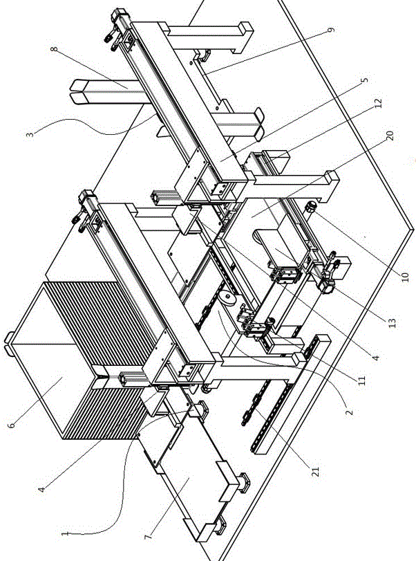
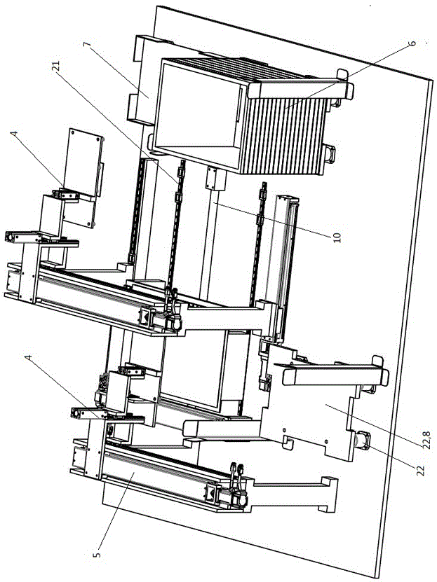
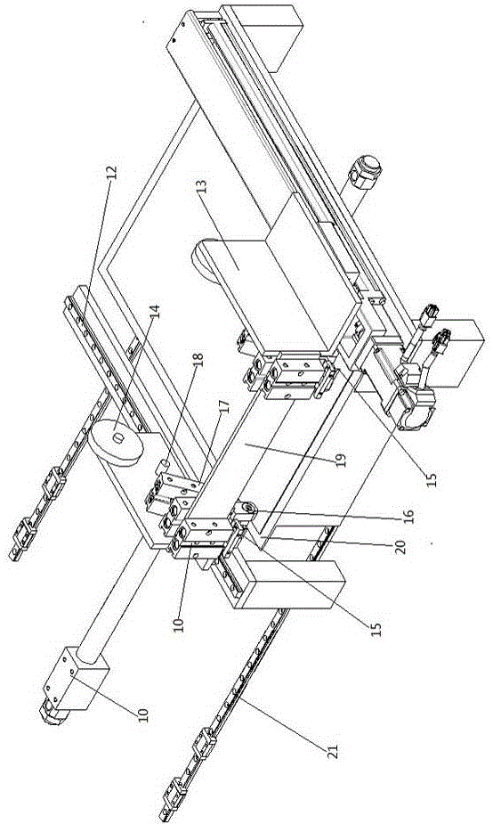
[0029] Such as figure 1 , figure 2 , image 3 with Figure 4 As shown, a guide frame gluing machine includes: loading area 1, gluing area 2 and unloading area 3 connected by a suction cup robot 4,
[0030] -The loading area 1 includes a first warehouse 6 and a second warehouse 7, and the unloading area 3 includes a third warehouse 8. The first warehouse 6, the second warehouse 7 and the third warehouse 8 are all equipped with a lifting platform 9 and a lifting platform 9 The upper is connected to the cylinder 10, the lifting frame 22 is connected to the lifting platform 9
[0031] -The glue application area 2 is provided with at least one glue application mechanism 11, the glue application mechanism 11 is arranged on the guide rail 12, the glue application mechanism 11 is provided with a fixed plate 13, and the fixed plate 13 is provided with a glue roller 14 at one end and a cutter at the other end 15. The pressure rubber roller 16 and the rubber guide roller 17, the cutter 15, the pressure rubber roller 16 and the rubber guide roller 17 are all connected with an air cylinder 10, and the air cylinder 10 corresponding to the rubber guide roller 17 is arranged obliquely.
[0032] From one end to the other end of the fixed plate 13 is provided with a rubber release roller 14, a rubber guide roller 17, a pressure roller 16 and a cutter 15 in sequence, and the extension direction of the fixed plate 13 is consistent with the extension direction of the guide rail 12.
[0033] The first compartment 6 and the second compartment 7 are stacked with pedestal frames and FPC substrates respectively. Each time the manipulator 4 sucks a pedestal frame, the lifting platform 9 rises by the thickness of the pedestal frame to ensure that the pedestal frame at the top of the first warehouse 6 is always located At the same height, the lifting platform 9 at the lower part of the FPC substrate also performs the same movement; similarly, after the third warehouse 8 does not put a bonded pedestal FPC substrate assembly, the lifting platform 9 drops a thickness distance. The above operations can facilitate the manipulator 4 to pick and place materials at the same height each time.
[0034] The first compartment 6 and the second compartment 7 are located at the other end of the track 21, so that the manipulator 4 can sequentially take out a pedestal frame and an FPC substrate and put it on the sliding plate 20 nearby, which is convenient for accurate and fast placement of the pedestal frame and FPC substrate. place.
[0035] The film is put on the rubber roll 14 and the direction and position of the rubber strip unwinding is guided by the guide post 18 and the rubber roller 17, and the rubber strip is accurately unwound at the joint between the guide frame and the FPC substrate, so that the rubber strip reaches the predetermined position .
[0036] The air cylinder 10 expands and contracts, and the rubber guide roller 17 is pressed on the preliminarily pasted rubber strip, and the gluing mechanism 11 is driven by the screw rod to move along the guide rail 12, so that the rubber guide roller 17 is exactly along the rubber strip movement defense line to compact the rubber strip On the guide frame.
[0037] Then it is pressed and held by the rubber guide roller 17, and the cutter 15 is driven by the air cylinder 10 to press down and cut the rubber strip.
[0038] The two sets of oppositely arranged glue application mechanisms 11 can form two sets of simultaneous glue application, and the glue application efficiency is higher.
[0039] The inclined arrangement of the cylinder 10 corresponding to the rubber guide roller 17 can guide and tighten the unwound rubber strip, which is convenient for glue application.
[0040] The fixing plate 13 is also provided with a guide post 18, and the guide post 18 is arranged between the rubber release roller 14 and the rubber guide roller 17.
[0041] The glue application area 2 is provided with two sets of glue application mechanisms 11, and the two sets of glue application mechanisms 11 are arranged oppositely.
[0042] The two groups of glue applying mechanisms 11 are connected together by a connecting plate 19, so that the two groups of glue applying mechanisms 11 form a linkage structure on the guide rail 12.
[0043] The glue application area 2 also includes a slide plate 20, which is arranged on the rail 21, and the guide rail 12 is arranged between the feeding area 1 and the glue application area 2. The slide plate 20 is driven by the cylinder 10 to move along the track 21, and the slide plate 20 can be located on the track 21. The glue mechanism 11 is directly below.
[0044] A suction cup is provided at the bottom of the manipulator 4, and the suction cup can suck the guide frame and the FPC substrate.
[0045] The manipulator 4 is installed on a frame 5 that is arranged across the frame 5, a mobile module is installed on the frame 5, and the manipulator 4 is moved by the mobile module.
[0046] The above is based on the ideal embodiment of the present invention as inspiration, and through the above description, relevant personnel can make various changes and modifications within the scope of the technical idea of ​​the present invention. The technical scope of the present invention is not limited to the content of the specification, and the technical scope must be determined according to the scope of the claims.

PUM

no PUM

Description & Claims & Application Information

We can also present the details of the Description, Claims and Application information to help users get a comprehensive understanding of the technical details of the patent, such as background art, summary of invention, brief description of drawings, description of embodiments, and other original content. On the other hand, users can also determine the specific scope of protection of the technology through the list of claims; as well as understand the changes in the life cycle of the technology with the presentation of the patent timeline. Login to view more.

Similar technology patents

Novel tape adhering machine

ActiveCN102674069AImprove glue application efficiencysimple structure
Owner:POLYGON AUTOMATION TECH CHENGDU

Winding device

ActiveCN109216746AImprove precision controlImprove glue application efficiency
Owner:DONGGUAN ARECONN PRECISION MACHINERY

Automatic rubberizing equipment, method for tearing rubber ring body paper and automatic rubberizing method

PendingCN111299082AImprove glue application efficiencySticking effect is stable
Owner:深圳亿和模具制造有限公司

Adhesive bonding mechanism and device

PendingCN111710916AImprove glue application efficiencySimple structure
Owner:GUANGDONG LYRIC ROBOT INTELLIGENT AUTOMATION CO LTD

Adhesive sticking device

PendingCN110311148Asmooth processImprove glue application efficiency
Owner:GUANGDONG LYRIC ROBOT INTELLIGENT AUTOMATION CO LTD

Classification and recommendation of technical efficacy words

  • Improve glue application efficiency

Novel tape adhering machine

ActiveCN102674069AImprove glue application efficiencysimple structure
Owner:POLYGON AUTOMATION TECH CHENGDU

Automatic rubberizing equipment, method for tearing rubber ring body paper and automatic rubberizing method

PendingCN111299082AImprove glue application efficiencySticking effect is stable
Owner:深圳亿和模具制造有限公司

Adhesive sticking device

PendingCN110311148Asmooth processImprove glue application efficiency
Owner:GUANGDONG LYRIC ROBOT INTELLIGENT AUTOMATION CO LTD

Winding device

ActiveCN109216746AImprove precision controlImprove glue application efficiency
Owner:DONGGUAN ARECONN PRECISION MACHINERY

Adhesive bonding mechanism and device

PendingCN111710916AImprove glue application efficiencySimple structure
Owner:GUANGDONG LYRIC ROBOT INTELLIGENT AUTOMATION CO LTD
Why Eureka
Try Eureka