Hydraulic clamping mechanism

A hydraulic clamping and pressure technology, which is applied in the direction of expanding the mandrel, etc., can solve the problems that the geometric shape and size of the inner hole are greatly affected, defective products are reworked or scrapped, and the contact surface of the inner hole is uneven, etc., to achieve production assistance Short time, product quality assurance, fast and convenient loading and unloading of workpieces

Inactive Publication Date: 2016-05-11
赵慧霞
View PDF0 Cites 7 Cited by
  • Summary
  • Abstract
  • Description
  • Claims
  • Application Information

AI Technical Summary

Problems solved by technology

[0002] At present, the machining of sleeve parts generally adopts axial center positioning, which uses elastic plastic as the main pressure transmission medium, and its elasticity rises unevenly, making the inner hole contact surface of sleeve parts uneven, especially in the production and processing sleeve In the process of cylindrical thin-walled workpieces, it has a great influence on the geometric shape and size of the inner hole, resulting in defective products, reworked products or waste products

Method used


Image

  • Hydraulic clamping mechanism

Examples


Embodiment Construction

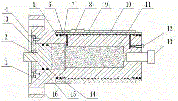
[0012] figure 1 The shown hydraulic clamping mechanism includes a base body 1, a piston 2 at one end of the middle hole of the base body 1, the piston 2 can move axially in the middle hole of the base body 1, and the other end is blocked by a second screw 13; The outside is provided with thread groove 8, elastic sleeve 10 and fixing hole 17. The thread groove 8 and the elastic sleeve 10 are closely matched. The screw 12 is blocked, and the middle hole and the thread groove 8 of the whole base body 1 are filled with pressure transmission medium to form a closed oil circuit. The elastic sleeve 10 is provided with a positioning sleeve 7 and a workpiece 9 .

[0013] The pressure transmission medium 11 is hydraulic oil, or other synthetic fluids that can transmit pressure.

[0014] In the middle hole of the base body 1 where the piston 2 is fixed by the baffle plate 3, a third sealing ring 15 and a fourth sealing ring 14 are arranged between the middle hole of the base body 1 and ...


PUM


Abstract

The invention relates to a hydraulic clamping mechanism, which comprises a base body, a piston, an elastic sleeve, sealing rings, a positioning sleeve and pressure transferring media. The hydraulic clamping mechanism is characterized in that a step-shaped middle hole is formed in the middle part of the base body; the piston is arranged at one end of the middle hole of the base body, and can move in the axial direction in the middle hole of the base body; the other end of the middle hole of the base body is sealed and plugged by a second screw; a threaded groove, an elastic sleeve and a fixing hole are arranged in the outer part of the base body; the threaded groove and the elastic sleeve are tightly matched; the starting end of the threaded groove communicates with the base body hole; the ending end of the threaded groove communicates with an oil opening; the oil opening is sealed and plugged by a first screw; the threaded groove and the middle hole of the whole base body are fully filled with the pressure transferring media; a sealed oil path is formed; and the positioning sleeve and a workpiece are arranged on the elastic sleeve. The hydraulic clamping mechanism has the advantages that the centering precision is high; the workpiece mounting and dismounting are fast and convenient; the influence on the deformation quantity of an inner hole of the workpiece is small; the production auxiliary time is short; the production efficiency is improved; the production cost is reduced; the product quality is guaranteed; and the hydraulic clamping mechanism is particularly suitable for processing sleeve type workpieces.

Description

technical field [0001] The invention belongs to mechanical processing technology equipment, in particular to a hydraulic clamping mechanism used on a hydraulic lathe or a numerical control machine tool. Background technique [0002] At present, the machining of sleeve parts generally adopts axial center positioning, which uses elastic plastic as the main pressure transmission medium, and its elasticity rises unevenly, making the inner hole contact surface of sleeve parts uneven, especially in the production and processing sleeve In the process of cylindrical thin-walled workpieces, the geometric shape and size of the inner hole are greatly affected, resulting in defective products, reworked products or waste products. The invention relates to a hydraulic clamping mechanism. Through the principle of hydraulic transmission, in a closed container, the pressure applied to the still liquid will be transmitted to all points of the liquid at the same time in equal value. A closed ...

Claims


Application Information

Patent Timeline
Patent Type & Authority Applications(China)
IPC IPC(8): B23B31/40
Inventor 赵慧霞
Owner 赵慧霞
Why Eureka
Try Eureka