Pneumatic material taking mechanical arm

A technology for retrieving manipulators and driving mechanisms, which is applied in the direction of manipulators, program-controlled manipulators, chucks, etc., can solve the problems of complex displacement mechanisms, increased control difficulty, and high cost, and achieve the effect of simple overall structure

Inactive Publication Date: 2016-05-11
GUANGDONG FXD INTELLIGENT EQUIP CO LTD
View PDF6 Cites 13 Cited by
  • Summary
  • Abstract
  • Description
  • Claims
  • Application Information

AI Technical Summary

Problems solved by technology

However, the existing displacement mechanism composed of a motor and its driven traveling mechanism is relatively complicated and heavy, and the cost is high
Moreover, in order to realize the opening and closing of the clamping finger group, the clamping driver usually fixes one of the clamping fingers and drives the other clamping finger to move closer or farther away from the fixed clamping finger. This kind of clamping method cannot be clamped in the centering mode with the workpiece to be clamped, and precise positioning is required, which greatly increases the difficulty of control

Method used


Image

  • Pneumatic material taking mechanical arm
  • Pneumatic material taking mechanical arm
  • Pneumatic material taking mechanical arm

Examples


Embodiment Construction

[0019] It should be noted that, in the case of no conflict, the embodiments in the present application and the features in the embodiments can be combined with each other. The present application will be further described in detail below in conjunction with the drawings and specific embodiments.

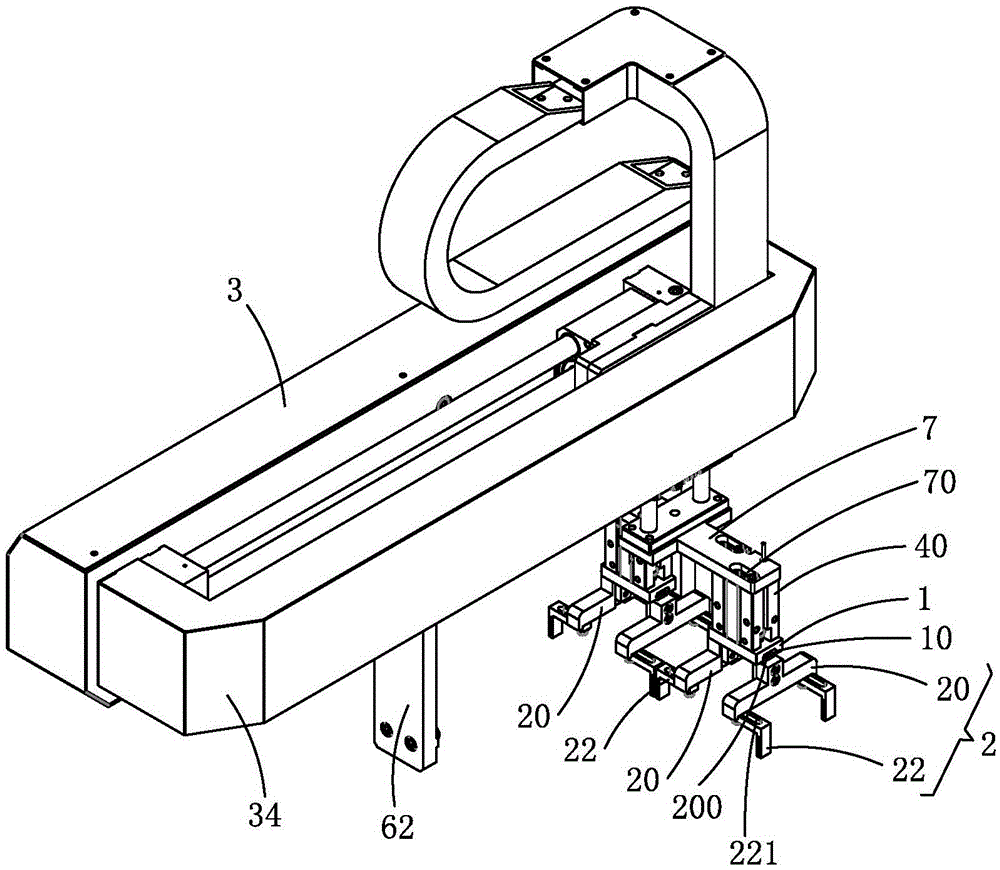
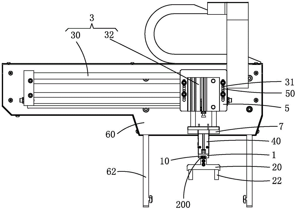
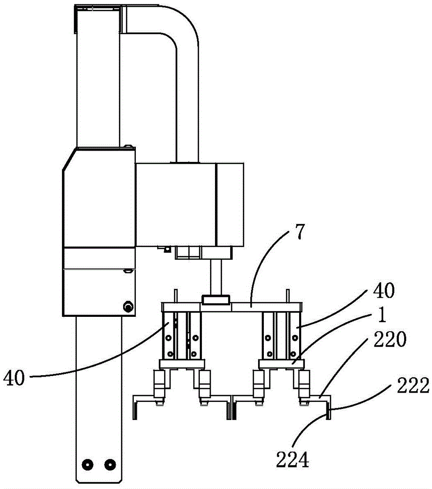
[0020] Such as Figure 1 to Figure 3 As shown, the present invention provides a pneumatic reclaiming manipulator, including a substrate 1, gripping fingers 2 movable in pairs on the substrate 1, a displacement mechanism 3 that drives the substrate 1 to move back and forth between different stations, and drives the same The clamping drive mechanism (not labeled) of the two clamping fingers of the pair.

[0021] The displacement mechanism 3 is mounted on a support plate 60 , and the support plate 60 is mounted on a corresponding support platform (not shown) by means of a support frame 62 . The displacement mechanism 3 includes a rodless cylinder assembly 30 installed on the support pl...


PUM


Abstract

The invention provides a pneumatic material taking mechanical arm. The mechanical arm comprises a base plate, clamping fingers, a displacement mechanism and a clamping driving mechanism for driving the clamping fingers to be opened and closed; the displacement mechanism comprises a rodless air cylinder assembly and a guide rod air cylinder assembly; the rodless air cylinder assembly is arranged in the Y axis direction, and the guide rod air cylinder assembly is arranged on a movable block of the rodless air cylinder assembly and is arranged in the Z-axis direction; the base plate and the movable block of the guide rod air cylinder assembly are relatively fixedly connected, a sliding rail is arranged on the base plate, and each pair of clamping fingers comprises two transverse supports arranged on the sliding rail in a sliding manner; a plurality of mounting holes are formed in each transverse support, two mounting holes are each provided with a clamping finger unit in a locking manner, and the transverse supports of the same pair of clamping fingers and the clamping finger units are symmetrically arranged; and the clamping driving mechanism comprises a clamping air cylinder arranged in the Z axis direction and a transmission assembly which is arranged between the tail end of a piston rod of the clamping air cylinder and the top ends of the transverse supports so as to drive the two transverse supports of each pair of clamping fingers and the clamping finger units on the two transverse supports to synchronously move in an opposite or backing manner. The pneumatic material taking mechanical arm is simple in overall structure and high in applicability.

Description

technical field [0001] The invention relates to the technical field of automatic handling of production lines, in particular to a pneumatic reclaiming manipulator. Background technique [0002] In order to improve the production efficiency of assembly line assembly operations, reduce the labor intensity of personnel, improve the safety of operations and the stability of product quality, the use of manipulators has been gradually promoted in the production process. The manipulators can cooperate with assembly line operations to complete the product between different stations. Moving action. [0003] Existing manipulators mainly include a base plate, a set of clamping fingers installed on the base plate for directly clamping the workpiece, a displacement mechanism for driving the base plate and the clamping fingers to move back and forth between different stations, and a set of clamping fingers for driving the clamping fingers. Sets open and close to correspond to the clampin...

Claims


Application Information

Patent Timeline
Patent Type & Authority Applications(China)
IPC IPC(8): B25J9/14B25J15/10
CPCB25J9/14B25J15/10
Inventor 侯立新
Owner GUANGDONG FXD INTELLIGENT EQUIP CO LTD
Why Eureka
Try Eureka