Tapping equipment for machining automobile oil pan guard plate, and working method thereof

A technology for oil pans and automobiles, applied in metal processing equipment, drilling/drilling equipment, metal processing machinery parts, etc., can solve the problems of small range of movement adjustment, poor precision, poor flexibility, etc., to achieve compression and fixation Precise location, high precision and quality, and improved breadth of effects

Inactive Publication Date: 2021-01-01
马鞍山贺辉信息科技有限公司
View PDF8 Cites 2 Cited by
  • Summary
  • Abstract
  • Description
  • Claims
  • Application Information

AI Technical Summary

Problems solved by technology

[0005] The purpose of the present invention is to solve the poor flexibility of the existing drilling equipment, the components used to load the guard plate on the drilling equipment cannot be flexibly moved, and it is not convenient for the staff to fix the guard plate on the drilling equipment. Drilling treatment; the existing drilling equipment is slow in efficiency and poor in precision for drilling the oil pan guard plate, and when the drilling equipment is drilling the oil pan guard plate, the position of the oil pan guard plate is prone to damage. Offset, which seriously affects the quality of drilling equipment for the oil pan guard; the existing drilling equipment cannot quickly drill holes of different sizes on the oil pan guard; and the existing drilling equipment The drill bit can be moved and adjusted in a small range, and the use of hole-drilling equipment is limited. It can only be used for drilling oil pan guards of the same size and size. Drilling equipment and working method for guard plate processing

Method used


Image

  • Tapping equipment for machining automobile oil pan guard plate, and working method thereof
  • Tapping equipment for machining automobile oil pan guard plate, and working method thereof
  • Tapping equipment for machining automobile oil pan guard plate, and working method thereof

Examples


Embodiment Construction

[0041] The technical solutions of the present invention will be clearly and completely described below in conjunction with the embodiments. Apparently, the described embodiments are only some of the embodiments of the present invention, not all of them. Based on the embodiments of the present invention, all other embodiments obtained by persons of ordinary skill in the art without creative efforts fall within the protection scope of the present invention.

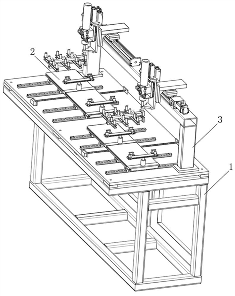
[0042] see Figure 1-11 As shown, a hole-drilling device for the processing of automobile oil pan guard plate includes a support frame 1, two supporting platforms 2 and a moving drill platform 3, and the two supporting platforms 2 are respectively arranged on two sides of the top of the supporting frame 1. side, and one end of the top of the support frame 1 is provided with a moving drill floor 3;

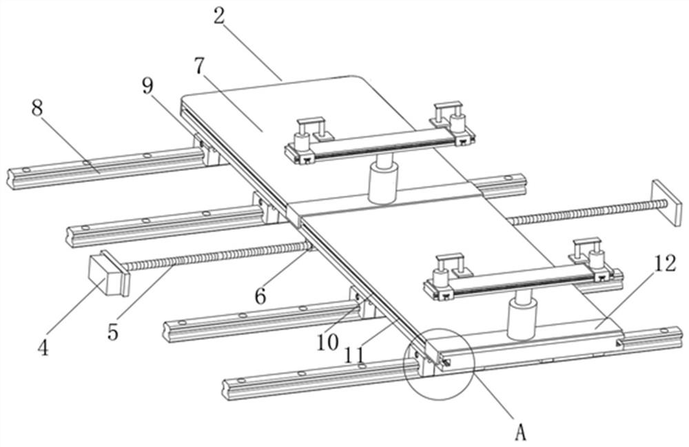
[0043] The supporting table 2 includes a motor-4, a sleeve rail 8 and a slide plate-7. One end of the middle part of the supp...


PUM


Abstract

The invention discloses tapping equipment for machining an automobile oil pan guard plate, and a working method thereof. The tapping equipment comprises a supporting frame, two supporting tables and adrill moving table; the two supporting tables are arranged on the two sides of the top of the supporting frame separately, and the drill moving table is arranged at one end of the top of the supporting frame; each supporting table comprises a motor I, a sleeve rail and a sliding disc I; and the motor I is arranged at one end of the middle part of the supporting table, and one end of the motor I is rotatably connected with a lead screw I through an output shaft. The tapping equipment has the beneficial effects that four drilling bases are arranged on each rotary disc, and drill bits in different sizes and models can be installed on each drilling base; it is guaranteed that the equipment can be used for rapidly drilling holes in different diameters in an oil pan guard plate, and the use diversity of the equipment and the efficiency of drilling holes in different oil pan guard plates are improved; the equipment is higher in tapping precision and efficiency for oil pan guard plates in different sizes; and the equipment is high in working automation degree, has good social benefits, and is suitable for popularization and application.

Description

technical field [0001] The invention relates to a hole-drilling device for processing an automobile oil pan guard plate, in particular to a hole-drilling device for processing an automobile oil sump guard plate and a working method thereof, belonging to the technical field of flour processing equipment applications. Background technique [0002] In the process of automobile assembly, the oil pan guard is indispensable. The oil pan guard is installed under the automobile oil pan, which has a good effect of preventing and protecting the oil pan. [0003] When processing the oil pan guard plate of the automobile, the pre-marked position of the oil pan guard plate must be drilled and drilled with the drilling equipment to ensure that the protruding components on the chassis It can pass through the hole of the guard plate, so that the guard plate can be better adapted to the chassis of the car, and the firmness of the guard plate assembled to the car is improved. [0004] The ex...

Claims


Application Information

Patent Timeline
Patent Type & Authority Applications(China)
IPC IPC(8): B23Q3/08B23B39/16B23B41/00B23Q5/40
CPCB23Q3/082B23B41/00B23B39/16B23Q5/40
Inventor 赵云卫凯袁辉方茹陈峰卫寿彬许丽君
Owner 马鞍山贺辉信息科技有限公司
Why Eureka
Try Eureka