
Hollow interlayer steel tube concrete column base joint

A technology for steel pipe concrete columns and concrete columns, which is applied in the direction of columns, pier columns, pillars, etc., can solve the problems of increased construction time and cost, insufficient shear and pull-out bearing capacity, and reduced rigidity, so as to improve shear and Pull-out bearing capacity, good pull-out resistance and shear resistance, and the effect of avoiding stress concentration

Active Publication Date: 2016-05-11
BEIJING UNIV OF TECH
View PDF6 Cites 8 Cited by
  • Summary
  • Abstract
  • Description
  • Claims
  • Application Information

AI Technical Summary

Problems solved by technology

Since the stiffness of the exposed joint only depends on the action of the anchor bolts, once the anchor bolts yield, the stiffness of the joint will decrease rapidly, unless a large number of anchor bolts and a sufficiently thick foot plate are used, which will greatly increase the construction time and cost; for embedded column foot joints, the stiffness of the joints will increase with the increase of the buried depth. Although this design can release the high stress on the anchor bolts, it will produce a concentration on the concrete contact between the joint and the foundation Stress, especially for piers with large height-to-width ratio or tall bridge piers, the shear and pull-out bearing capacity may be insufficient

Method used


Image

  • Hollow interlayer steel tube concrete column base joint
  • Hollow interlayer steel tube concrete column base joint
  • Hollow interlayer steel tube concrete column base joint

Examples


Embodiment 1

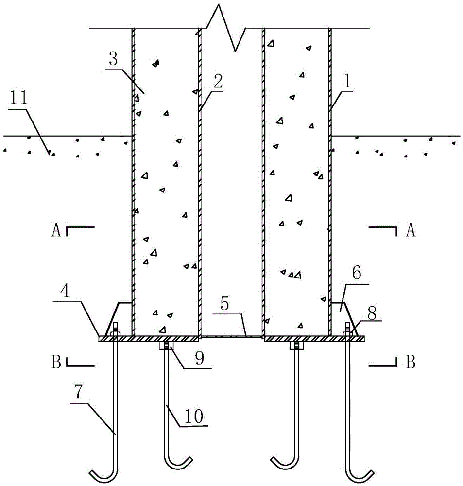
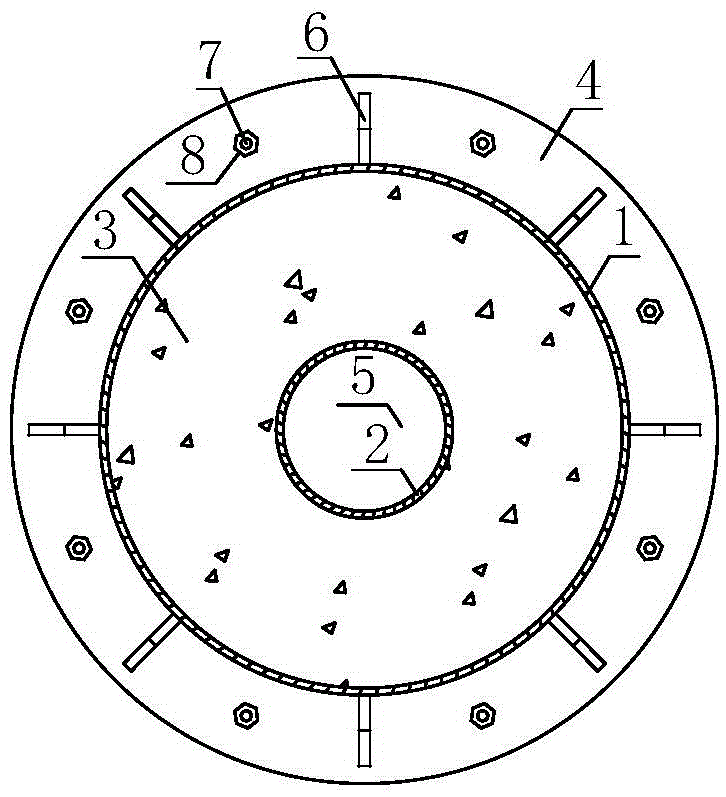
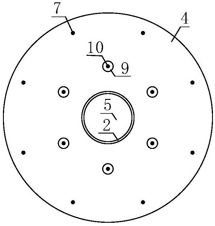
[0025] As attached figure 1 Shown: First, the foot plate 4 is processed. The center of the foot plate 4 is processed into a hollow according to the outer contour of the inner steel pipe 2, and the outside of the foot plate 4 is drilled according to the diameter of the outer anchor bolt 7, and the drilling positions are evenly arranged on the outer side of the outer steel pipe 1. At the same time, a special nut 9 is prefabricated and welded on the foot plate 4. A foot plate 4 is welded to the bottom of the outer steel pipe 1 and the inner steel pipe 2, the lower surface of the inner steel pipe 2 exceeds the upper surface of the foot plate 4 to reach between the upper surface and the lower surface of the foot plate, and the bottom inner wall of the inner steel pipe 1 is welded with a sealing plate 5. Then, concrete 3 is poured between the outer steel pipe 1 and the inner steel pipe 2. At the junction of the outer steel pipe 1 and the foot plate 4, the outer steel pipe 1 is welded...


PUM


Abstract

The invention discloses a hollow interlayer steel tube concrete column base joint, and relates to the technical field of building and bridge engineering. Concrete is filled between an outer steel tube and an inner steel tube, so that a hollow interlayer concrete column is formed; the hollow interlayer concrete column is inserted into a foundation platform; the bottoms of the steel tubes are connected with a base board; rib plates are connected with the outer steel tube and the base board and are distributed on the periphery of the outer steel tube; a close plate is connected with the inner wall of the bottom of the inner steel tube; outer foundation bolts penetrate through an extend-out punching position of the base board and are distributed among the rib plates; the bottoms of the outer foundation bolts are bent outward; bottoms of inner outer foundation bolts are bent inward. The hollow interlayer steel tube concrete column base joint has the advantages that the foundation bolts are arranged inside and outside a column base, force at the upper part of a structure can be uniformly transferred to a foundation, and the phenomenon of stress concentration is avoided; the center of the base board is hollowed, so that a space for welding of the base board and the inner steel tube is formed; axial force transferred from the upper part of a column is directly transferred to the foundation through the base board, and a bending moment is transferred to the foundation platform through the base board and the foundation bolts; the combined action of the inner foundation bolts and the outer foundation bolts has good pulling resistance effect and shearing resistance effect.

Description

Technical field [0001] The invention relates to the technical field of construction and bridge engineering, in particular to a novel hollow sandwich steel tube concrete column foot joint. Background technique [0002] Hollow sandwich steel tube concrete is a new type of steel-concrete composite structure proposed on the basis of steel tube concrete. Its cross-sectional form is formed by pouring concrete in the sandwich between two layers of concentric steel tubes, leaving space inside the inner steel tube . In recent years, it has been popularized and applied in engineering. In addition to the advantages of solid concrete filled steel tube with high bearing capacity and good plasticity, it also has the characteristics of light weight, good earthquake resistance and high rigidity. This makes the hollow sandwich steel tube concrete have great advantages in the applications of high bridge piers, high-rise building vertical members, offshore platform supports, etc. [0003] The colum...

Claims


Application Information

Patent Timeline
IPC IPC(8): E04B1/18E04C3/36
CPCE04B1/185E04C3/36
Inventor 韩强贾振雷温佳年王雪剑
Owner BEIJING UNIV OF TECH
Learn More