Physical simulation huff-puff production experimental method and device

A technology of physical simulation and experimental method, applied in the fields of fluid production, earthwork drilling, wellbore/well components, etc., can solve the problems of time-consuming, labor-intensive operation, inconvenience, etc., and achieve flexible and convenient operation, easy injection, and easy operation. The effect of mining

Active Publication Date: 2016-05-11
CHINA NAT OFFSHORE OIL CORP +1
View PDF5 Cites 20 Cited by
  • Summary
  • Abstract
  • Description
  • Claims
  • Application Information

AI Technical Summary

Problems solved by technology

Among them, when performing the throughput simulation experiment, because the stimulation process must realize both injection and regurgitation, sufficient elasticity is required, and the compressibility of water, crude oil, and rock itself in the formation is very small, so that the indoor throughput The model of the physical simulation experiment is usually large, and a large enough space is needed to establish the elastic energy. Therefore, it is time-consuming, labor-intensive and inconvenient to complete a throughput experiment.

Method used


Image

  • Physical simulation huff-puff production experimental method and device
  • Physical simulation huff-puff production experimental method and device

Examples


Embodiment 1

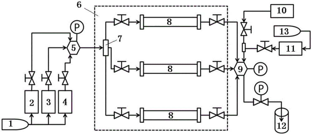
[0041] like figure 1 As shown, the experimental device of the present embodiment includes a booster pump 1, and the output end of the booster pump 1 communicates with the inlets of a water intermediate container 2, an oil intermediate container 3 and a gas intermediate container 4 through pipelines respectively, and the water The outlets of the intermediate container 2, the oil intermediate container 3 and the gas intermediate container 4 communicate with a six-way valve 5 through pipelines respectively. The six-way valve 5 communicates with a four-way valve 7 arranged in the thermostat 6 through a pipeline, and the four-way valve 7 communicates with the inlets of three rock core models 8 arranged in the thermostat 6 respectively through three pipelines. The outlets of each rock core model 8 communicate with the same six-way valve 9 through pipelines respectively. The six-way valve 9 communicates with a steam generator 10, a chemical intermediate container 11 and a receiver 1...

Embodiment 2

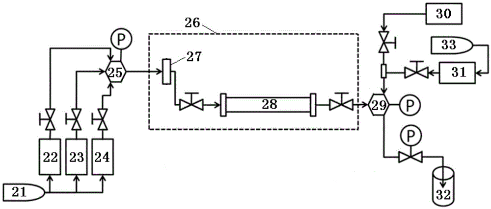
[0049] like figure 2 As shown, the experimental device of the present embodiment comprises a booster pump 21, and the output end of the booster pump 21 communicates with the inlets of a water intermediate container 22, an oil intermediate container 23 and a gas intermediate container 24 respectively through pipelines, and the water The outlets of the intermediate container 22 , the oil intermediate container 23 and the gas intermediate container 24 communicate with a six-way valve 25 through pipelines respectively. The six-way valve 25 communicates with a four-way valve 27 arranged in the thermostat 26 through a pipeline, and the four-way valve 27 communicates with the inlet of a rock core model 28 arranged in the thermostat 26 through the pipeline, and the core model 28 The outlet communicates with a six-way valve 29 through a pipeline. The six-way valve 29 communicates with a steam generator 30, a chemical intermediate container 31 and a receiver 32 respectively through th...


PUM


Abstract

The invention relates to a physical simulation huff-puff production experimental method and device. The method is characterized by comprising the steps that 1, a core model for an experiment is vacuumized; 2, simulation formation water is sucked into the core model till the core model absorbs water to reach saturation; 3, crude oil is injected into the core model till no simulation formation water is drained out of the core model; 4, according to the solution gas-oil ratio data of a target oil field to be measured and core model output simulation formation water volume, the volume of gas needing to be injected into the core model is worked out; 5, the gas is injected into the core model; 6, huff-puff fluid is injected into the core model, the core model is closed, and a soaking process is simulated; 7, after experiment time is up, the core model is opened for huff-puff fluid and crude oil spurt, and one-time physical simulation huff-puff production experiment is completed. Experiments in different huff-pull ways can be carried out, influence effects of different injection parameters or parameter quantized comparison effect data, and a reliable evaluation platform is provided for thickened oil field exploitation in different huff-puff ways.

Description

technical field [0001] The invention relates to an experimental method and device for physically simulating oil production by stimulation, and belongs to the field of oil field development experiments. Background technique [0002] Huff and puff oil recovery refers to the injection of huff and puff fluids (such as steam, chemical agents, etc.) After fully functioning, the well will be opened for production after the brine is completed. At this time, the injection fluid staying in the formation will flow out of the wellhead together with the crude oil to complete the blowing process. In the process of huff and puff production, parameters such as injected fluid type, fluid injection volume, soaking time and fluid injection velocity will all affect the development effect of the oilfield, so it is necessary to determine reasonable injection parameters. At present, the determination of injection parameters mainly relies on theoretical calculations, numerical method simulations, ...

Claims


Application Information

Patent Timeline
Patent Type & Authority Applications(China)
IPC IPC(8): E21B43/22E21B43/24E21B43/16
CPCE21B43/16E21B43/168E21B43/24
Inventor 崔盈贤杨光何春百赵文森赵娟田冀朱玥珺吕鑫薛新生王大威
Owner CHINA NAT OFFSHORE OIL CORP
Why Eureka
Try Eureka