
Diesel engine single overhead camshaft driven valve rocker mechanism

A valve rocker arm, diesel engine technology, applied in the direction of machine/engine, valve device, mechanical equipment, etc., can solve the problem that cannot meet the high speed, high reinforcement of diesel engine, increase the height and width of the whole diesel engine, and the axial height and transverse direction of the mechanism. The problem of large width, etc., achieves the effect of compact structure, improved service life, and small size of the mechanism.

Active Publication Date: 2016-05-11
FIRST TRACTOR
View PDF6 Cites 5 Cited by
  • Summary
  • Abstract
  • Description
  • Claims
  • Application Information

AI Technical Summary

Problems solved by technology

The common double overhead camshaft structure has a large number of parts, the processing and assembly process of each component of the mechanism is complicated, and the manufacturing is difficult; the axial height and lateral width of the mechanism are relatively large, which increases the height and width of the diesel engine
However, due to the complex structure, many parts, inconvenient disassembly and assembly, and poor control accuracy, the traditional central camshaft transmission mechanism cannot meet the requirements of high-speed and high-strength diesel engines.

Method used


Image

  • Diesel engine single overhead camshaft driven valve rocker mechanism
  • Diesel engine single overhead camshaft driven valve rocker mechanism
  • Diesel engine single overhead camshaft driven valve rocker mechanism

Examples


Embodiment Construction

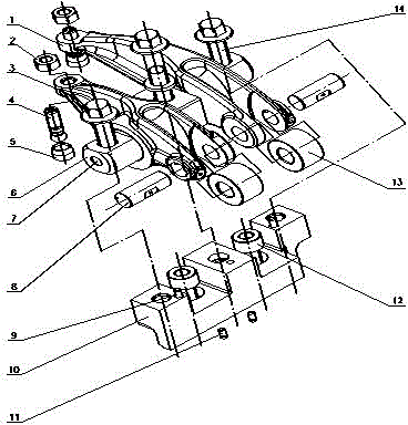
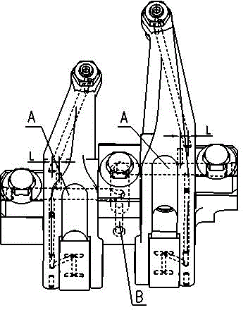
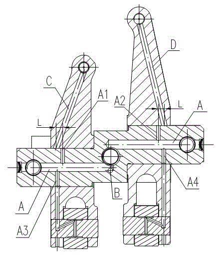
[0011] Below in conjunction with accompanying drawing, the present invention will be further described: as Figure 1~3 As shown, the diesel engine overhead single camshaft drives the valve rocker arm mechanism, including: exhaust rocker arm 1, nut 2, intake rocker arm 3, rocker arm ball head 4, rocker arm ball head seat 5, rocker arm shaft 6, Plug piece 7, rocker arm rolling pin 8, first positioning pin 9, rocker arm shaft seat 10, second positioning pin 11, fixing screw 12, rocker arm roller 13 and bolt 14; rocker arm ball seat 5 is set on the rocker arm On the arm ball head 4, the top of the rocker ball head seat 5 is extruded with the shape of the rocker arm ball head 4, and the rocker arm ball head 4 can rotate freely in the rocker arm ball head seat 5. Screw the threaded end of the rocker ball head 4 into the threaded hole at the valve end of the rocker arm, and install the nut 2 on the top of the threaded end of the rocker ball head 4 where the end face of the rocker arm...


PUM


Abstract

The invention discloses a diesel engine single overhead camshaft driven valve rocker mechanism. The mechanism comprises an exhaust rocker, an intake rocker, rocker ball heads, rocker ball head seats, a rocker shaft, rocker rolling pins, a rocker shaft seat and rocker rolling columns, wherein the rocker ball head seats sleeves the rocker ball heads; the threaded ends of the rocket ball heads are screwed in the threaded holes at the valve ends of the rockers; nuts are arranged at the tops of the threaded ends, exposed from the end faces of the rockers, of the rocker ball heads; the rocker rolling columns are arranged in slots at the cam ends of the rockers and are integrally connected with the rockers through the rocker rolling pins which are inserted in the inner holes at the cam ends of the rockers; a positioning pin is mounted on the bottom surface of the rocker shaft seat, an intake rocker mounting groove and an exhaust rocker mounting groove are milled in the top surface of the rocker shaft seat, and rocker shaft seat fixing bolts are arranged on the bottom surfaces of the grooves; the rocker shaft consists of a mounting boss in the middle and fixed shafts of the intake rocker and exhaust rocker at the two ends, and the both the two shaft ends are milled in the horizontal direction; the intake rocker and the exhaust rocker are respectively sleeved at two ends of the rocker shaft; and three bolts respectively penetrate through the two ends and the middle parts of the rocker shaft so as to fix the rocker shaft at the upper top surface of the rocker shaft seat and then the rocker shaft seat is positioned by the positioning pin.

Description

technical field [0001] The invention belongs to the field of internal combustion engines, and relates to an overhead single camshaft driven valve rocker arm mechanism of a diesel engine. Background technique [0002] At present, my country's emission requirements for vehicles are becoming more and more stringent, the application of vehicle after-treatment devices is becoming more and more extensive, and the requirements for the space utilization of the engine compartment are also getting higher and higher, all of which put forward higher requirements for the design of diesel engines . The common double overhead camshaft structure has a large number of parts, the processing and assembly process of each component of the mechanism is complicated, and the manufacturing is difficult; the axial height and lateral width of the mechanism are relatively large, which increases the height and width of the diesel engine. However, due to the complex structure, many parts, inconvenient di...

Claims


Application Information

Patent Timeline
IPC IPC(8): F01L1/18F01L1/053F01M9/10
Inventor 商潭苏谢克艳韦明慧魏明亮李康复周梅乞玉龙杜晓辉石坤鹏李灵敏
Owner FIRST TRACTOR
Learn More