Centrifugal fan and air conditioner

A centrifugal fan and air conditioner technology, applied in the direction of machines/engines, mechanical equipment, liquid fuel engines, etc., can solve problems such as airflow blockage at the inlet of the ventilation duct, affecting the working efficiency of the fan, and large dynamic noise of the wind wheel, so as to increase kinetic energy, Effect of reducing air separation phenomenon and suppressing growth of boundary layer thickness

Inactive Publication Date: 2016-05-11
GREE ELECTRIC APPLIANCES INC
View PDF8 Cites 8 Cited by
  • Summary
  • Abstract
  • Description
  • Claims
  • Application Information

AI Technical Summary

Problems solved by technology

[0003] The inventors have found that there are at least the following problems in the prior art: during the actual operation of the fan, air flow blockage is prone to occur at the inlet of the air duct, and low-energy fluid is easy to accumulate on the suction surface of the blade, forming The vortex with a large size will eventually cause the fluid to separate at the suction surface near the blade outlet, resulting in a large aerodynamic noise during the operation of the wind wheel, which seriously affects the working efficiency of the fan

Method used


Image

  • Centrifugal fan and air conditioner
  • Centrifugal fan and air conditioner
  • Centrifugal fan and air conditioner

Examples


Embodiment Construction

[0025] Combine below Figure 1 ~ Figure 4 The technical solution provided by the present invention is described in more detail.

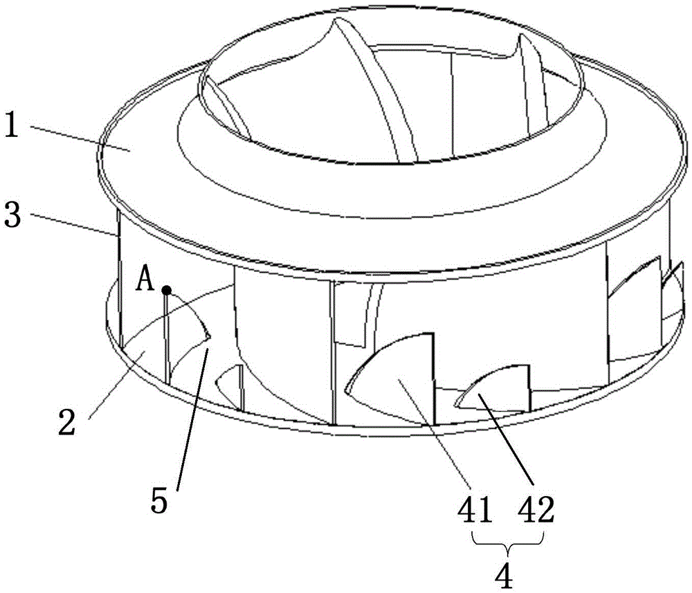
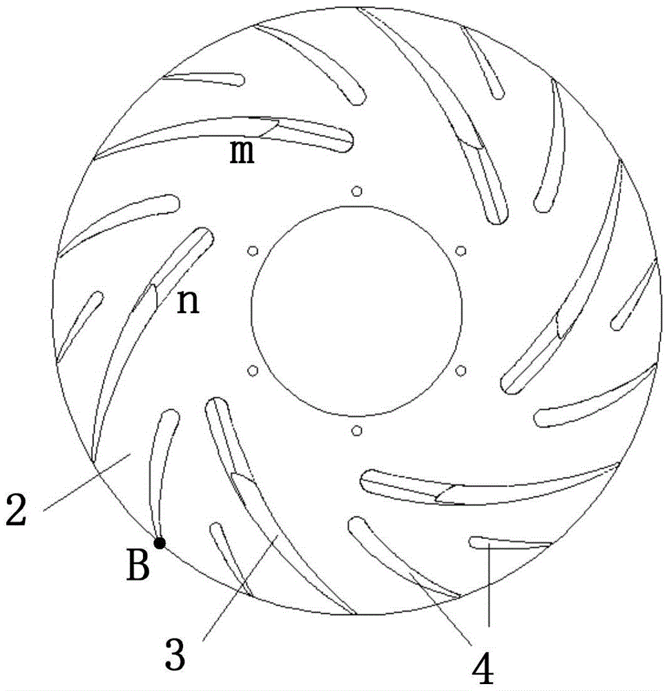
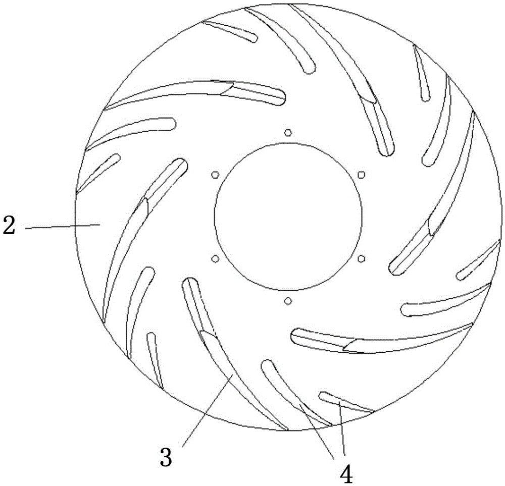
[0026] see figure 1 and figure 2 , Embodiment 1 of the present invention provides a centrifugal fan, which may specifically be a backward centrifugal fan. It includes a first disc 1, a second disc 2, and blades 3 arranged between the first disc 1 and the second disc 2, and a guide channel 5 is formed between two adjacent vanes 3; wherein, the guide channel 5 A deflector 4 is provided inside, and the deflector 4 is used to reduce the cross-sectional area of ​​the flow guide channel 5 so as to increase the air velocity in the guide channel 5 . The vanes 4 and the vanes 3 have the same shape but different sizes.

[0027] In this embodiment, the first disc 1 is the front disc, and the second disc 2 is the rear disc.

[0028] In the above technical solution, a guide vane 4 is added to the guide channel between the blades 3 of the centrifugal fan, s...


PUM


Abstract

The invention discloses a centrifugal fan and an air conditioner, relates to the field of air conditioning and aims to lower fluid flow loss and the noise of the centrifugal fan. The centrifugal fan comprises a first plate, a second plate and vanes arranged between the first plate and the second plate, and a flow deflection channel is formed between every two adjacent vanes; flow deflectors are arranged in the flow deflection channels; the flow deflectors and the vanes are identical in shape but different in size. According to the technical scheme, the flow deflectors are arranged in the flow deflection channels additionally, channels at the front edges of original vanes are narrowed, fluid in the flow deflection channels is accelerated, the kinetic energy of the fluid on the suction surfaces is effectively increased, low-energy fluid is effectively prevented from gathering, growth of the boundary layer thickness is restrained, the airflow separation phenomenon on the suction surfaces of the vanes is reduced, and finally the fluid flow loss and the aerodynamic noise of the centrifugal fan can be lowered.

Description

technical field [0001] The invention relates to the field of air conditioning, in particular to a centrifugal fan and an air conditioner. Background technique [0002] The backward centrifugal fan includes a front disk, a rear disk and blades arranged between the front disk and the rear disk, and an air duct is formed between the blades. [0003] The inventors have found that there are at least the following problems in the prior art: during the actual operation of the fan, air flow blockage is prone to occur at the inlet of the air duct, and low-energy fluid is easy to accumulate on the suction surface of the blade, forming The large vortex finally causes the fluid to separate at the suction surface near the outlet of the blade, which leads to a large aerodynamic noise during the operation of the wind wheel, which seriously affects the working efficiency of the fan. Contents of the invention [0004] One of the objectives of the present invention is to provide a centrifu...

Claims


Application Information

Patent Timeline
Patent Type & Authority Applications(China)
IPC IPC(8): F04D29/28F04D29/30F04D29/66
CPCF04D29/281F04D29/30F04D29/666F04D29/667
Inventor 张苏北曹雷刘洋刘中杰邹建煌
Owner GREE ELECTRIC APPLIANCES INC
Why Eureka
Try Eureka