Infrared thermal imaging temperature measurement early warning device and system

A technology of infrared thermal imaging and temperature measuring devices, applied in measuring devices, signal transmission systems, thermometers, etc., can solve problems such as complicated installation, long construction period, and untestable temperature of wiring inside the switchgear

Inactive Publication Date: 2016-05-11
ZHENGZHOU HAIWEI OPTOELECTRONICS TECH CO LTD
View PDF4 Cites 5 Cited by
  • Summary
  • Abstract
  • Description
  • Claims
  • Application Information

AI Technical Summary

Problems solved by technology

[0003] 1. The temperature measurement characteristics of the traditional handheld infrared thermal imager require the operator to patrol. Because it cannot be transmitted, it is impossible to test the narrow and confined space, such as the temperature of the wiring inside the switch cabinet, which cannot be tested, and cannot be transmitted in real time;
[0004] 2. Using infrared thermal imaging on-line monitoring system is too expensive and difficult to promote, and it is impossible to test in small spaces;
[0006] 4. The distributed optical fiber temperature measurement system also has the disadvantages that the optical fiber is easy to break, easy to break, and not resistant to high temperature
The accumulation of dust will easily reduce the insulation, there will be hidden dangers of creepage, and the safety will be poor; in addition, the installation is more complicated and the construction period is long

Method used


Image

  • Infrared thermal imaging temperature measurement early warning device and system
  • Infrared thermal imaging temperature measurement early warning device and system
  • Infrared thermal imaging temperature measurement early warning device and system

Examples


Embodiment Construction

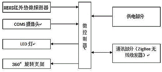
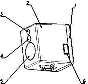
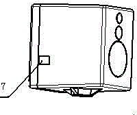
[0013] The technical solutions adopted by the present invention to solve the technical problems are: the system will develop and expand the interface based on MEMS multi-element detectors; the temperature measuring probe circuit design, plate making, welding, assembly and so on. Three light channels (infrared main channel, visible light channel and illumination channel) are used simultaneously. Develop the probe installation model; design the probe package model, make a suitable back cover (1) and insulating main shell (2), and make the size as small as possible to facilitate installation in the cabinet.

[0014] The system and the probe realize wireless communication, using zigbee technology. Accurately and reliably transmit visible light image data and infrared temperature data to the system in real time.

[0015] The device is connected with a tuner, the tuner is connected with a router, and the router is connected with a computer terminal. Customize related transport pro...


PUM


Abstract

The invention discloses a novel noncontact wireless area temperature measurement device and method suitable for the conditions of enclosed space, such as a switch cabinet, a box transformer substation, a ring network cabinet and a dispatching center machine room. The temperature measurement device comprises a temperature measurement probe, a 360-degree rotatable adsorption type mounting bracket and a power supply module. According to the noncontact wireless area imaging temperature measurement early warning device and method, real-time monitoring of the enclosed space, such as the switch cabinet, the box transformer substation, the ring network cabinet and the dispatching center machine room, can be realized, and a thermal imaging monitoring terminal arranged in the cabinet can transmit data to a computer terminal by a coordinator through a router. The computer terminal can display infrared videos in real time according to the temperature data. Besides, temperature analysis can also be performed. Area analysis can be performed on infrared thermal images, and early warning and alarm of a situation that temperature exceeds the threshold can be performed and real-time inquiring of alarm records can also be performed; besides, historical curves of monitoring points can also be reflected so as to perform preliminary judgment on the temperature measurement development trend of equipment.

Description

technical field [0001] The present invention is a new type of non-contact wireless area temperature measurement which is suitable for being installed in closed space conditions such as switch cabinets, box transformers, ring network cabinets, cables, and dispatching center computer rooms, and realizes temperature analysis and early warning in device areas. system. Background technique [0002] Whether the power equipment is safe to operate and whether there are potential hidden dangers, temperature is a key indicator to measure. At present, the application of temperature measurement in electricity at home and abroad mainly has the following characteristics: [0003] 1. The temperature measurement characteristics of the traditional handheld infrared thermal imager require the operator to patrol. Because it cannot be transmitted, it is impossible to test the narrow and confined space, such as the temperature of the wiring inside the switch cabinet, which cannot be tested, and...

Claims


Application Information

Patent Timeline
Patent Type & Authority Applications(China)
IPC IPC(8): G01J5/00G08C17/02G01K1/02G01K1/024
Inventor 焦战威唐旭涛易剑楠闫林赵晓光
Owner ZHENGZHOU HAIWEI OPTOELECTRONICS TECH CO LTD
Why Eureka
Try Eureka