Track detection device and method

A track detection and track technology, which is applied in the field of track detection, can solve the problems of inability to realize real-time interactive review, inability to accurately stabilize track parameters, etc., and achieve the effects of batch production, short detection time, and reduced labor intensity.

Active Publication Date: 2017-01-04
XIANGYANG HONGWEI AIRCRAFT
View PDF10 Cites 14 Cited by
  • Summary
  • Abstract
  • Description
  • Claims
  • Application Information

AI Technical Summary

Problems solved by technology

[0005] However, due to the structure of the car body and rollers, as well as the layout of distance sensors, gauge sensors, and inclination sensors, the detection trolley still cannot accurately and stably measure the detection and data of track parameters, and at the same time cannot realize real-time interactive consultation with testing personnel.

Method used


Image

  • Track detection device and method
  • Track detection device and method
  • Track detection device and method

Examples


Embodiment Construction

[0035] In order to make the object, technical solution and advantages of the present invention clearer, the present invention will be further described in detail below in conjunction with the accompanying drawings and embodiments. It should be understood that the specific embodiments described here are only used to explain the present invention, not to limit the present invention. In addition, the technical features involved in the various embodiments of the present invention described below may be combined with each other as long as they do not constitute a conflict with each other.

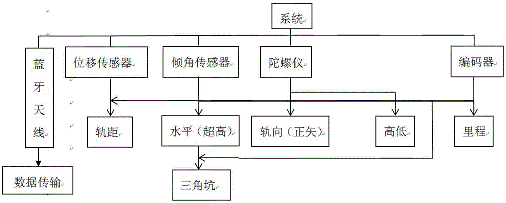
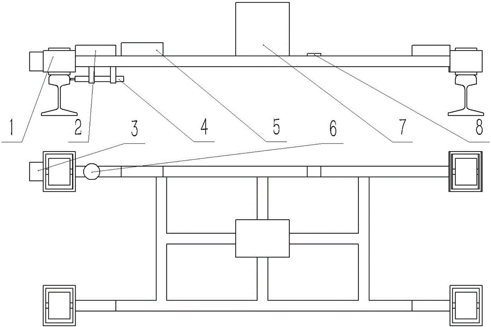
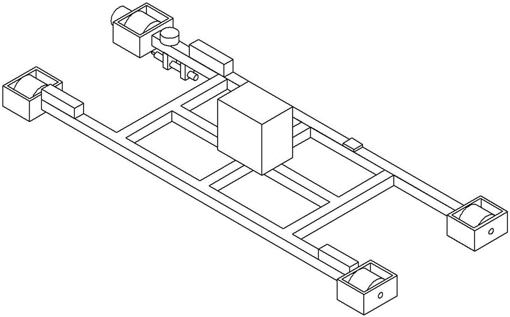
[0036] figure 1 It is a schematic structural diagram of a track detection device provided by an embodiment of the present invention, figure 2 is a 3D schematic of the device. Such as Figure 1-2 As shown, a track detection device according to an embodiment of the present invention includes a detection device car body 1, a drive motor 2, an encoder 3, a displacement sensor 4, an inclination s...


PUM


Abstract

The invention discloses a track detection device. The track detection device comprises a vehicle body, encoders, displacement sensors, tilt angle sensors I and tilt angle sensors II, wherein the vehicle body comprises two cross beams perpendicular to the track direction and a rack which is arranged between the two cross beams and is of a grid framework structure; the encoders are arranged at the tail of at least one end of at least one cross beam and used for measuring the traveling distance in vehicle body detection; the displacement sensors are arranged on the tip of at least one end of at least one cross beam, arranged on the lower surfaces of the ends of the cross beams and used for measuring a track gauge change component in the traveling process of the vehicle body; the tilt angle sensors I are arranged on at least one cross beam, located on the upper surfaces of the ends of the cross beams and used for measuring the vehicle body tilt angle change in the traveling process, and thus a vehicle body level value can be calculated; and the tilt angle sensors II are arranged on at least one cross beam, located on the upper surfaces of the ends of the cross beams and used for measuring angle changes of the course angle and the rolling angle in the traveling process of the vehicle body, and thus the track direction and height value can be calculated according to the principles of attitude measurement and control and trajectory measurement.

Description

technical field [0001] The invention belongs to the field of track detection, and more particularly relates to a device and method for track detection. Background technique [0002] With the development of railway traffic in the direction of high speed and high density, the time when railway maintenance workers can effectively work without a car is getting shorter and shorter, and the daily static inspection work of the line is becoming more and more difficult. According to the requirements of the line maintenance and repair rules, the line static inspection must be mandatory in a fixed period. The detected parameters are: gauge, level (superelevation), rail direction (positive vector), height, triangular pit and mileage. [0003] The traditional detection method is to use a mechanical gauge and a manual dragging method, which requires a lot of work. In recent years, a track inspection instrument has appeared, and the track inspection instrument is manually pushed to move ...

Claims


Application Information

Patent Timeline
Patent Type & Authority Applications(China)
IPC IPC(8): B61K9/08G08C17/02
CPCB61K9/08G08C17/02
Inventor 王杰薛富利雷自力赵俊王萌薛龙康吉
Owner XIANGYANG HONGWEI AIRCRAFT
Why Eureka
Try Eureka