Electric transformer

A technology of power transformers and transformers, which is applied in the field of high-voltage electric power, can solve problems such as restrictions on the application and promotion of power transformers, and achieve the effects of firm strength, stable reliability, vibration reduction, and stability and reliability

Inactive Publication Date: 2016-05-11
胡妍
View PDF3 Cites 2 Cited by
  • Summary
  • Abstract
  • Description
  • Claims
  • Application Information

AI Technical Summary

Problems solved by technology

[0004] Most of the existing power transformers are installed by means of flange installation or bonding, and the installation position generally needs to be reserved, so the application and promotion of power transformers are more restricted

Method used


Image

  • Electric transformer
  • Electric transformer
  • Electric transformer

Examples


Embodiment 1

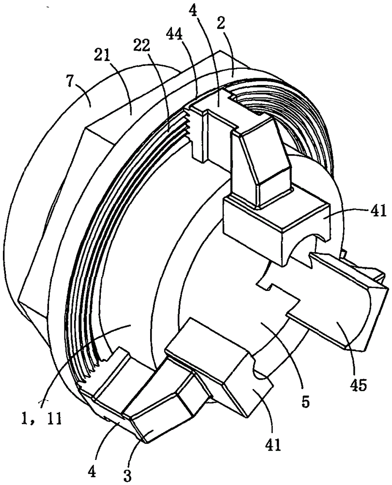
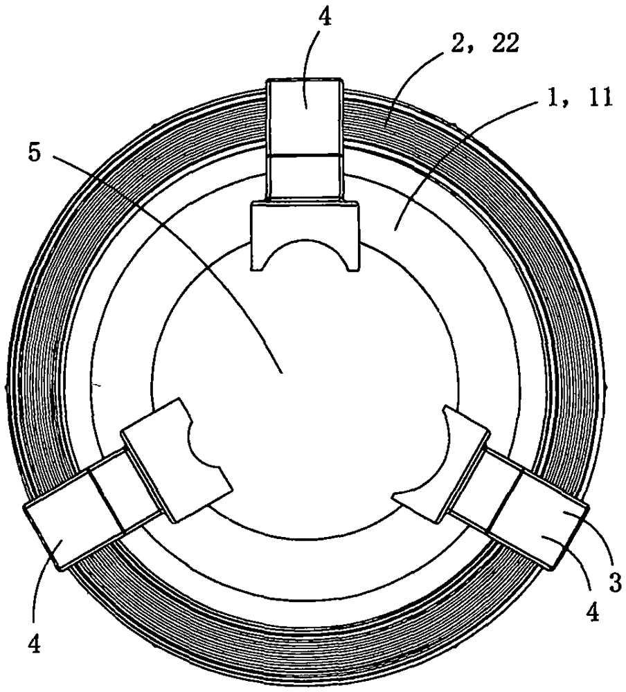
[0018] This embodiment is a power transformer, see Figure 1 to Figure 7 As shown, it includes a base body 1, a flat nut 2, a set of pressure jaw assembly 3 and a transformer 7; the pressure jaw assembly includes three pressure jaws 4; the base body is provided with a slide tube 11, a radial guide limit set on the slide tube The positioning hole 12 and the stopper 13 arranged on the outer peripheral wall of the slide tube protrude outward along the radial direction of the slide tube;

[0019] The plane nut 2 is annular, and the plane nut is slidingly sleeved on the outer peripheral wall of the base sliding tube 11; the transformer is also annular, and is fixedly sleeved on the outer peripheral wall of the base sliding tube;

[0020] The shape of the block is ring-shaped, and the block is located at the middle end of the slide tube of the base body;

[0021] The transformer and the plane nut are separated on both sides of the block, and the radial guide limit hole 12 plane nut...

Embodiment 2

[0036] This embodiment is basically the same as Embodiment 1, the difference is: see Figure 8As shown, in order to be used as a splicing clamp for insulated power cables in this embodiment, a plurality of punctures 42 are also provided on the inner wall of the pressing plate. The piercing protrudes radially inwardly along the base slide tube 11 . The existence of puncture can effectively connect power without stripping the insulated power cables. Embodiment 1 can not be provided with puncture because what is connected is bare wire.

[0037] Each puncture is made during casting; in practice, the puncture can also be made in other ways; for example, a plurality of installation slots are provided on the inner wall of the pressure plate part, and then the puncture pieces made by punching are embedded In a corresponding mounting slot, the puncture piece includes a mounting portion and a stabbing blade, the mounting portion is embedded in the mounting slot, and the stabbing blade...


PUM


Abstract

The invention discloses an electric transformer. The electric transformer comprises a base body, a plane nut, a pressing claw assembly and a transformer body. The pressing claw assembly comprises three pressing claws. The base body is provided with a sliding pipe, a check platform and three radial guide limiting holes. The plane nut and the transformer body are arranged on the peripheral wall of the sliding pipe of the base body in a sleeved mode. The plane nut is located between the radial guide limiting holes and the check platform. The pressing claws are located in the corresponding radial guide limiting holes. Each pressing claw is provided with a pressing plate part, a guide sliding block part and a driving thread part. A fastening part is arranged on the peripheral wall of the plane nut, and the plane nut is provided with a plane thread part matched with the driving thread parts of the pressing claws in a meshed mode. When rotating back and forth, the plane nut drives the pressing claws to get close to or keep away from one another towards the center of the sliding pipe. The three radial guide limiting holes are evenly distributed in the peripheral wall of the sliding pipe of the base body, and penetrate through the wall of the sliding pipe in the radial direction of the sliding pipe of the base body. The driving thread parts are arranged at the side ends, adjacent to the plane nut, of the guide sliding block parts. The electric transformer is convenient to install.

Description

technical field [0001] The invention belongs to the technical field of high-voltage electric power, and in particular relates to a power transformer. Background technique [0002] The power transformer is a transformer suitable for converting large voltage into small voltage or converting large current into small current in 1kv to 220kv power system for easy measurement, protection and use. [0003] Most of the existing power transformers are electromagnetic induction transformers, the working principle is the same as that of the transformer, and the basic structure is also the iron core and the primary and secondary windings. The main functions of power transformers are as follows: convert high voltage into low voltage, convert large current into small current, and then use it for measurement, control and protection. This can not only increase the range of measuring instruments, facilitate the standardization of instruments, reduce the voltage and current of control and pr...

Claims


Application Information

Patent Timeline
Patent Type & Authority Applications(China)
IPC IPC(8): H01F27/06H01F38/20H02G7/02F16L3/10
CPCH01F27/06F16L3/10H01F38/20H02G7/02
Inventor 胡妍
Owner 胡妍
Why Eureka
Try Eureka