
LED display driving circuit

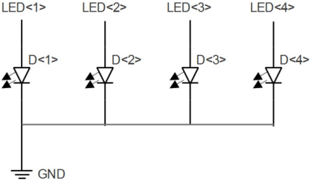
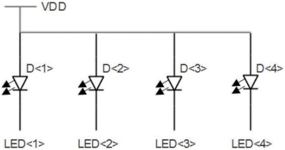
A display drive and circuit technology, applied in the field of LED display drive circuits, can solve the problems of occupying I/O resources, achieve multi-function, save I/O resources, and reduce costs

Active Publication Date: 2016-05-11
SHENZHEN FM ELECTRONICS GRP CO LTD
View PDF5 Cites 2 Cited by
  • Summary
  • Abstract
  • Description
  • Claims
  • Application Information

AI Technical Summary

Problems solved by technology

The biggest shortcoming of the existing technology is that the number of interfaces needs to be consistent with the number of display bits, which takes up valuable I / O resources

Method used


Image

  • LED display driving circuit
  • LED display driving circuit
  • LED display driving circuit

Examples


Embodiment Construction

[0024] image 3 The LED display driving circuit provided by this specific embodiment is shown. from image 3 It can be seen that the LED display driving circuit includes a power supply terminal connected in series, a three-state driver, a driving module and a ground terminal, and the three-state driver has three states of outputting high level, outputting low level and outputting high resistance. In this specific embodiment, the three-state driver is composed of a P-type metal oxide semiconductor effect transistor and an N-type metal oxide semiconductor effect transistor in series, through the P-type metal oxide semiconductor effect transistor and the N-type metal oxide semiconductor effect transistor The different states of the semiconductor effect transistor are used to control the different states of the LED port, so as to achieve the purpose of controlling the driving circuit.

[0025] Figure 4 It is the anode driving module provided by the embodiment of the pre...


PUM


Abstract

The invention relates to an electronic circuit field and particularly relates to an LED display driving circuit. The LED display driving circuit comprises a power source end, a tri-state driver, a driving module and a ground end which are connected in series, wherein the tri-state driver has three states, including high level output, low level output and high resistance output. Through changing a circuit requiring four LED ports for driving four LED lamps, only two LED ports are needed, so 50% I / O resources are saved, the cost is greatly reduced, moreover, through the LED display driving circuit, when the quantity of the LED ports is not changed, more functions can be realized.

Description

technical field [0001] The invention relates to the field of electronic circuits, in particular to an LED display driving circuit. Background technique [0002] LED is the abbreviation of light-emitting diode, which is a kind of semiconductor diode, which can convert electrical energy into light energy. Like ordinary diodes, light-emitting diodes are composed of a P pole and an N pole, and also have unidirectional conductivity. When a forward voltage is applied to the light-emitting diode, the holes injected from the P region to the N region and the electrons injected from the N region to the P region are respectively connected to the electrons in the N region and the vacancies in the P region within a few microns near the PN junction. Hole recombination, resulting in spontaneous emission of fluorescence. The energy states of electrons and holes are different in different semiconductor materials. The amount of energy released when electrons and holes recombine varies, and...

Claims


Application Information

Patent Timeline
Patent Type & Authority Applications(China)
IPC IPC(8): H05B33/08H05B44/00
CPCH05B45/00Y02B20/30
Inventor 董鑫杨奕
Owner SHENZHEN FM ELECTRONICS GRP CO LTD
Learn More