Metal-finger plugging board and manufacturing method thereof
A manufacturing method and gold finger technology, which is applied in the direction of electrical connection of printed components, printed circuit components, and formation of electrical connections of printed components, can solve the problems of increased resource consumption and production costs, increased gold finger thickness, and unfavorable gold finger insertion. Problems such as the structure of the pallet, to increase energy consumption and production costs, change the process and process, and ensure the effect of versatility
- Summary
- Abstract
- Description
- Claims
- Application Information
AI Technical Summary
Problems solved by technology
Method used
Image
Examples
Embodiment 1
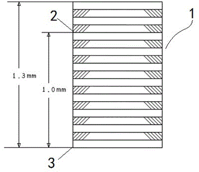
[0045] This embodiment provides a gold finger plug-in card board, which includes a 10-layer circuit board as an example, including a card board body 1 with 10 layers of circuit board layers and a gold finger 4 arranged on one side of the card body 1 , the golden fingers 4 are respectively electrically connected to the circuit board layer through the top finger wiring layer 2 and the bottom finger wiring layer 3 opposite to the top finger wiring layer 2, specifically as image 3 As shown, the top finger wiring layer 2 and the bottom finger wiring layer 3 of the golden finger 4 are respectively laid on the third circuit board of the circuit board layer (such as Figure 7 shown in the area of part C) and the bottom circuit board (as shown in Figure 9 (shown in the area of part E in the middle); along the stacking direction of the circuit board layer of the card main body 1, the thickness between the top of the top finger wiring layer 2 and the bottom of the bottom finger wir...
Embodiment 2
[0056] This embodiment provides a gold finger card board, which is a modification on the basis of Embodiment 1, the difference is that: Figure 10 As shown, the top finger wiring layer 2 and the bottom finger wiring layer 3 of the golden finger 4 are respectively laid on the top circuit board and the eighth circuit board of the circuit board layer.
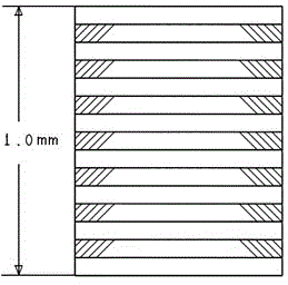
[0057] In this embodiment, the thickness between the top of the top finger wiring layer 2 and the bottom of the bottom finger wiring layer 3 is 1.0 mm, and the thickness of the cardboard main body 1 is 1.3 mm. Similarly, the above-mentioned thicknesses of 1.0 mm and 1.3 mm are only an example of this embodiment, and should not be understood as a limitation of this embodiment. If necessary, the top finger wiring layer 2 and the bottom finger wiring layer 3 The thickness between the bottoms can be other thicknesses, and the thickness of the card board main body 1 can also be set to an appropriate thickness according to needs. In ad...
Embodiment 3
[0066] This embodiment provides a gold finger card board, which is a modification on the basis of Embodiment 1, the difference is that: Figure 11 As shown, the top finger wiring layer 2 and the bottom finger wiring layer 3 of the golden finger 4 are respectively laid on the second-layer circuit board and the ninth-layer circuit board of the circuit board layer.
[0067] In this embodiment, the thickness between the top of the top finger wiring layer 2 and the bottom of the bottom finger wiring layer 3 is 1.0 mm, and the thickness of the cardboard main body 1 is 1.3 mm. Similarly, the above-mentioned thicknesses of 1.0 mm and 1.3 mm are only an example of this embodiment, and should not be understood as a limitation of this embodiment. If necessary, the top finger wiring layer 2 and the bottom finger wiring layer 3 The thickness between the bottoms can be other thicknesses, and the thickness of the card board main body 1 can also be set to an appropriate thickness according to...
PUM
 Abstract
Description
Claims
Application Information
 - R&D
- Intellectual Property
- Life Sciences
- Materials
- Tech Scout
- Unparalleled Data Quality
- Higher Quality Content
- 60% Fewer Hallucinations
Browse by: Latest US Patents, China's latest patents, Technical Efficacy Thesaurus, Application Domain, Technology Topic, Popular Technical Reports.
© 2025 PatSnap. All rights reserved.Legal|Privacy policy|Modern Slavery Act Transparency Statement|Sitemap|About US| Contact US: help@patsnap.com


