Vacuum Chuck Or Gripping Device

A technology of clamping device and clamping device, which is applied in the directions of positioning device, clamping, transportation and packaging, etc., can solve the problem of lateral sliding of the workpiece, and achieve the effect of reliable production, simple and efficient production

Active Publication Date: 2016-05-18
J SCHMALZ GMBH
View PDF9 Cites 0 Cited by
  • Summary
  • Abstract
  • Description
  • Claims
  • Application Information

AI Technical Summary

Problems solved by technology

Here too, the workpiece can slide laterally due to the lip structure

Method used


Image

  • Vacuum Chuck Or Gripping Device
  • Vacuum Chuck Or Gripping Device
  • Vacuum Chuck Or Gripping Device

Examples


Embodiment Construction

[0025] In the text below and in the figures, the same reference symbols are used in each case for identical and mutually corresponding features.

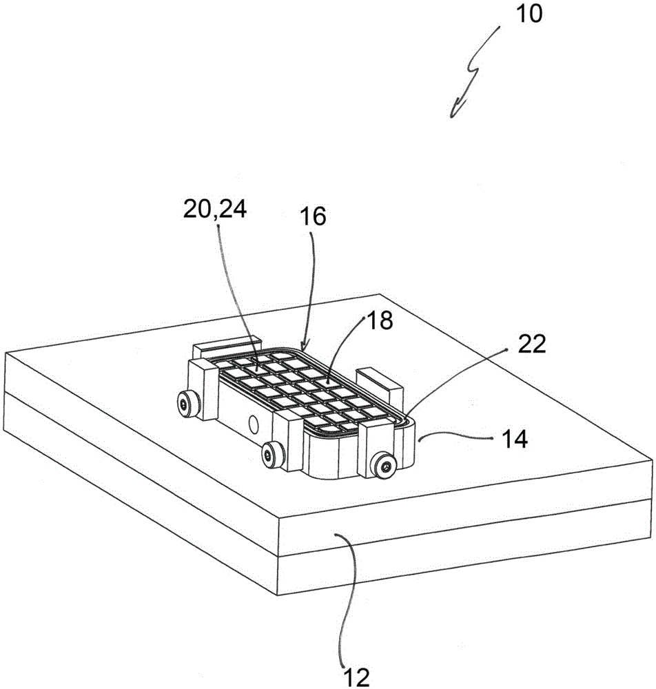
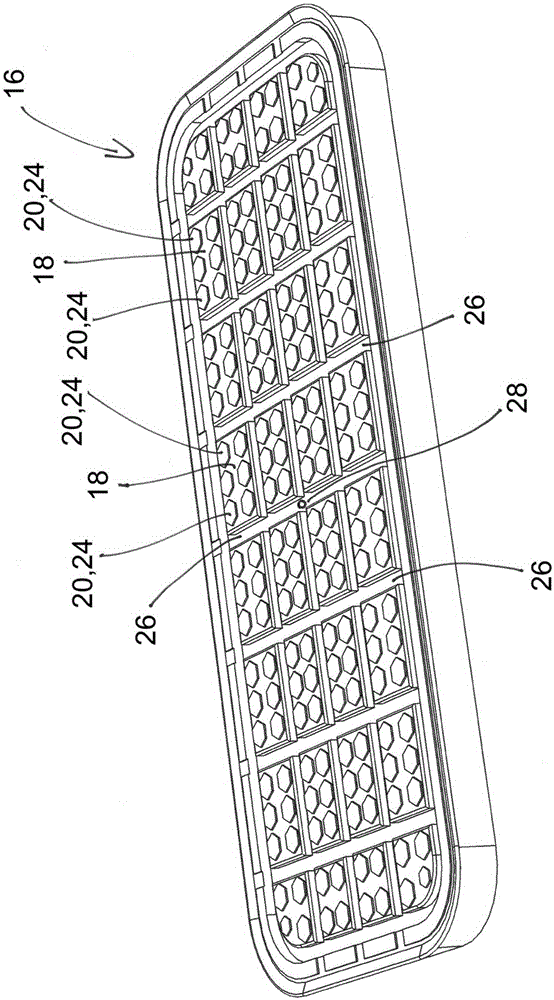
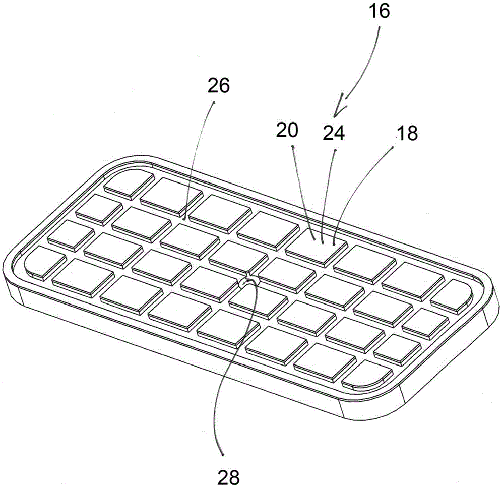
[0026] figure 1 A vacuum clamping device 10 is shown as an example, which is arranged on a table 12 of a processing device, not shown in detail. The vacuum clamping device 10 comprises a housing 14 with a vacuum supply system (not shown in detail), such as a vacuum chamber, arranged in the housing 14 . The housing 14 has an upper side which forms the suction surface 16 of the vacuum clamping device 10 , which is designed as a clamping surface in the example not shown. Adsorption surface 16 has suction port 28 (for example, see figure 2 , 3 ), through the suction port by means of a vacuum supply system, air can be sucked in, and thus the workpiece can be sucked onto the suction surface 16 .

[0027] The suction surface has a plurality of protruding regions 18 which provide contact regions 20 which, during operation of the device...


PUM

PropertyMeasurementUnit
Thicknessaaaaaaaaaa
Shore hardnessaaaaaaaaaa

Abstract

The invention relates to a vacuum chuck or gripping device, with a suction surface to which a held workpiece can be sucked, the suction surface has at least one bearing region, which rests while holding the workpiece at this. For positionally stable, friendly and slip-proof suction and holding of the workpiece, the contact region has a coating with an elastomer.

Description

technical field [0001] The invention relates to a vacuum clamping device or clamping device according to the preamble of claim 1 . Background technique [0002] Clamping or clamping devices of this type are used in particular to hold or lift flat objects during processing, for example holding or lifting flat materials which are stable in position, such as plates, flat plastic parts or plates. [0003] Special requirements are placed when processing workpieces with very smooth and / or delicate surfaces, such as viewing windows or dust covers for displays. In this case, slippage should be avoided during suction and subsequent processing of the held workpiece, and damage should be avoided during the suction process. [0004] It is basically known to arrange a foam lining on the suction surface. A corresponding device is described, for example, in DE 10 2006 050 970 A1. In particular, such foam facings serve to avoid damage to the workpiece to be sucked, in particular to suppr...

Claims


Application Information

Patent Timeline
IPC IPC(8): B23Q3/08
CPCB65G47/91B65G49/061B65G2249/04B23Q3/088
Inventor 拉尔夫·施托克布格尔
Owner J SCHMALZ GMBH
Why Eureka
Try Eureka