Composite brake disc for a vehicle disc brake

Pending Publication Date: 2021-11-04
CONTINENTAL TEVES AG & CO OHG
View PDF5 Cites 0 Cited by
  • Summary
  • Abstract
  • Description
  • Claims
  • Application Information

AI Technical Summary

Benefits of technology

The patent proposes a bracket design for brakes that improves safety and performance. A collar on the brake disk pot is designed to provide a strong and secure attachment for the brake friction ring, even when the friction ring is heated. The use of a steel material, particularly a high-alloy grade, makes the brake disk pot more resistant to rust and improves optical properties. The bracket design also includes a cooling system for the brake friction ring. These improvements result in a cost-effective, adjustable, lightweight, and strong brake assembly.

Problems solved by technology

This leads to more powerful brake systems and higher loading of the brake disks.
However, such different materials sometimes have very different physical properties, such as, for example, coefficients of thermal expansion, moduli of elasticity or corrosion resistances, and therefore joining said materials together is a challenge.
A disadvantage in addition to very high demands on production tools is a relatively low flexural strength, as a result of which the friction ring can easily tilt with respect to the brake disk pot.
A known undesirable phenomenon in brake disks is a heat-related deformation of the friction ring, what is referred to as shielding of the brake disk, which leads to a deterioration in the tribological quality.
The brake disk pot can lead to asymmetrical stresses and can intensify or even cause this effect.
Such a construction, however, considerably reduces the torsional rigidity of the shell and leads to the build-up of force and stress peaks, in particular in the transition region of the pot base into the shell.
This limits the permissible torque or the durability.
Furthermore, the pot base has to withstand more torsional stresses and therefore has to be made relatively thick.

Method used


Image

  • Composite brake disc for a vehicle disc brake

Examples


Embodiment Construction

The FIGURE

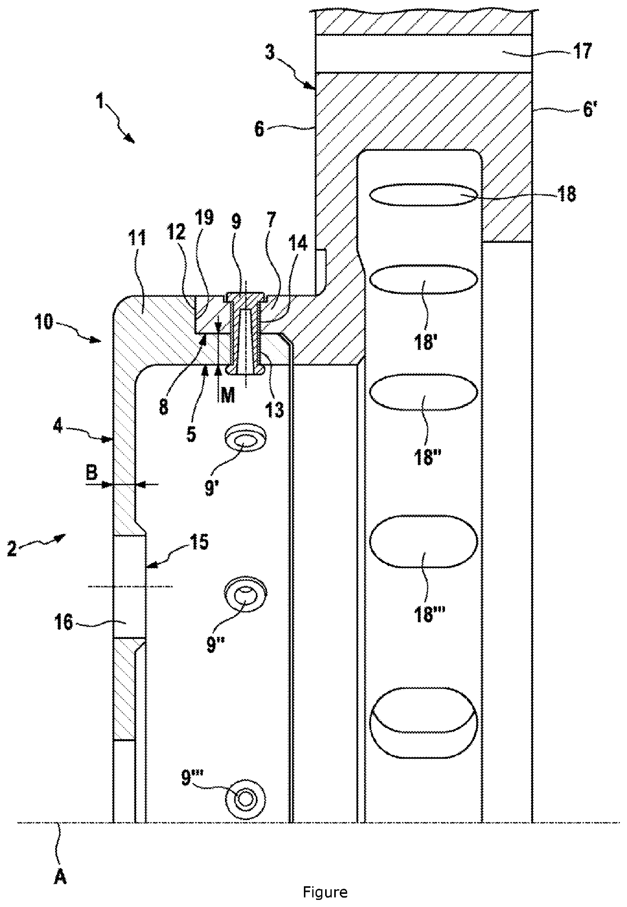
[0027]A composite brake disk 1 has a brake disk pot 2 which is preferably formed from steel, such as, for example, from C45, or from another high-alloy, rust-resistant or, particularly preferably, rustproof grade of steel.

[0028]The brake disk pot 2 has a multiply perforated, particularly thin-walled pot base 4 extending in the radial direction with respect to the axis of rotation A, and a circular-cylindrical pot shell 5 formed from the pot base 4 concentrically with respect to the axis of rotation A. The base thickness B is provided here so as to be less than the shell thickness M.

[0029]The pot base 5 is perforated by a plurality of connecting bores 16, customarily 4 or 5, which are provided for penetrating by wheel screws or wheel bolts for fastening the wheel to the wheel hub. In the embodiment shown, an encircling bead 15, which is axially pre-stretched in the direction of the friction ring 3 and locally increases the base thickness B, is formed in the region of the co...


PUM


Abstract

A composite brake disk for a vehicle disk brake, including a brake disk pot which is formed from a first material and is connected to a friction ring made of a different material, wherein the pot shell and a circular-cylindrical collar formed on the friction ring overlap in some regions in the radial direction in a connecting region and are penetrated by a plurality of connecting elements oriented substantially orthogonally with respect to the axis of rotation, wherein the composite brake disk is suitable for transmitting high mechanical and thermal loads in all operating states, while being simple to manufacture, and can also be formed with a particularly thin pot base and, for this purpose, enables the collar to engage radially on the outside around the pot shell in the connecting region.

Description

CROSS REFERENCE TO RELATED APPLICATIONS[0001]This application is the U.S. National Phase Application of PCT International Application No. PCT / EP2019 / 073855, filed Sep. 6, 2019, which claims priority to German Patent Application No. 10 2018 215 297.7, filed Sep. 7, 2018, the contents of such applications being incorporated by reference herein.FIELD OF THE INVENTION[0002]The invention relates to a multi-part composite brake disk for a vehicle disk brake, in particular for use in a passenger vehicle or a light commercial vehicle.BACKGROUND OF THE INVENTION[0003]Modern vehicles have increasingly higher weights and wheels with ever larger diameters. This leads to more powerful brake systems and higher loading of the brake disks.[0004]A brake disk is functionally customarily into a friction ring, which cooperates with brake pads and is provided for converting the kinetic energy into heat, and a brake disk pot for fastening the friction ring to a wheel hub and for transmitting torque.[0005...

Claims


Application Information

Patent Timeline
IPC IPC(8): F16D65/12
CPCF16D65/123F16D2065/1316F16D65/125F16D2065/1392F16D2065/1328F16D2200/0021
Inventor HOLLSTEIN, FRANKWELLER, RALPHVALENCIA BLAZQUEZ, ANDRES
Owner CONTINENTAL TEVES AG & CO OHG
Why Eureka
Try Eureka