Method for producing a unit consisting of eccentric rod and piston of a connecting rod of an internal combustion engine

a technology of eccentric rods and connecting rods, which is applied in the direction of connecting rod bearings, machines/engines, operating means/releasing devices of valves, etc., can solve the problems of simple and difficult problems, and achieve the effect of simple and reliable production and good articulated attachmen

Active Publication Date: 2020-02-11
DR ING H C F PORSCHE AG
View PDF8 Cites 0 Cited by
  • Summary
  • Abstract
  • Description
  • Claims
  • Application Information

AI Technical Summary

Benefits of technology

[0015]The second end of the eccentric rod is designed as a ball head that is inserted partially into a ball shell segment in the piston. The injection-molding tool is placed on a portion of the ball head that projects out of the ball shell segment of the piston, and the circumferentially closed retaining ring is formed between the piston, the portion of the ball head that projects out of the ball shell segment of the piston, and the injection-molding tool. Consequently, the assembly of the piston and eccentric rod can be produced in a particularly advantageous manner.
[0016]The injection-molding tool may be placed on the portion of the ball head that projects out of the ball shell segment of the piston in such a way that the ball head is pressed against the ball shell segment. The ball head together with the injection-molding tool then is displaced in a defined manner relative to the piston to set a defined gap between the ball head and ball shell segment. The circumferentially closed retaining ring then is formed by injection-molding between the piston, the portion of the ball head that projects out of the ball shell segment of the piston, and the injection-molding tool. The defined gap between the ball head and ball shell segment may be set so that no injection-molding material enters this gap during injection-molding. These details also serve for the particularly advantageous, simple and reliable production of the assembly of the eccentric rod and piston. The defined gap can ensure a good articulated attachment of the eccentric rod to the piston.

Problems solved by technology

However, difficulties have been posed in simply and reliably producing a unit consisting of eccentric rod and piston in which the eccentric rod is secured in the piston via a closed retaining ring.

Method used


Image

  • Method for producing a unit consisting of eccentric rod and piston of a connecting rod of an internal combustion engine
  • Method for producing a unit consisting of eccentric rod and piston of a connecting rod of an internal combustion engine

Examples


Embodiment Construction

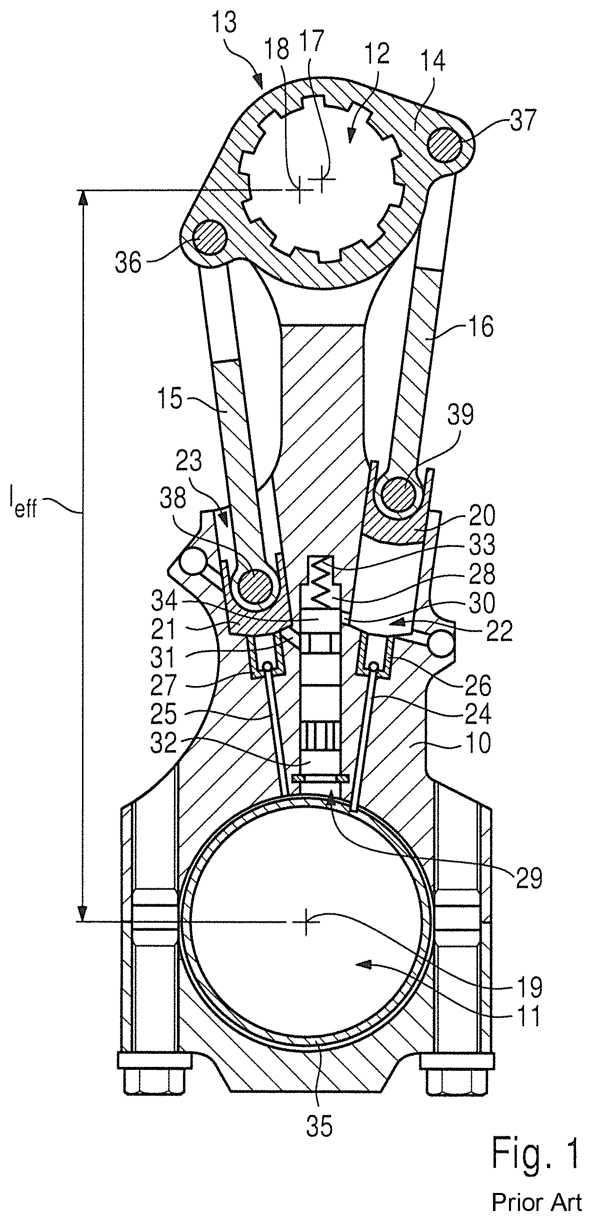
[0021]An internal combustion engine with an adjustable compression ratio has at least one, preferably a plurality of, cylinder(s). Each cylinder has a piston that is coupled to a crankshaft of the internal combustion engine by a connecting rod 10.

[0022]Each connecting rod 10 has a small end bearing eye 12 at one end and a big end bearing eye 11 at an opposite end. The respective connecting rod 10 acts by way of its big end bearing eye 11 on a crankshaft bearing pin of the crankshaft in such a way that a connecting rod bearing shell is positioned between the crankshaft bearing pin and the big end bearing eye, with a lubricating oil film being able to build up between the connecting rod bearing shell and the crankshaft bearing pin.

[0023]An internal combustion engine with an adjustable compression ratio has, in the region of each connecting rod 10, an eccentric adjusting device 13 for adjusting the effective connecting rod length of the respective connecting rod 10.

[0024]The eccentric ...


PUM

PropertyMeasurementUnit
compression ratioaaaaaaaaaa
lengthaaaaaaaaaa
hydraulic pressureaaaaaaaaaa

Abstract

A method is provided for producing an assembly of an eccentric rod (15, 16) and a piston (20, 21) of a connecting rod of an internal combustion engine having an adjustable compression ratio. The method includes providing an eccentric rod (15, 16) having a first end (36, 37) for attachment to an eccentric lever of an eccentric adjusting device of the connecting rod and a second end (38, 39) for attachment to a piston (20, 21) that can be guided in a hydraulic chamber of the connecting rod. The method then includes arranging the second end (38, 39) of the eccentric rod (15, 16) in the piston (20, 21); introducing an injection-molding tool (47) into the piston (20, 21); and injection-molding a circumferentially closed retaining ring (43) between the piston (20, 21), the second end (38, 39) of the eccentric rod (15, 16) and the injection-molding tool (47).

Description

CROSS REFERENCE TO RELATED APPLICATION[0001]This application claims priority under 35 USC 119 to German Patent Appl. No. 10 2017 116 122.8 filed on Jul. 18, 2017, the entire disclosure of which is incorporated herein by reference.BACKGROUNDField of the Invention[0002]The invention relates to a method for producing a unit of eccentric rod and piston of a connecting rod of an internal combustion engine having an adjustable compression ratio.[0003]Related Art DE 10 2010 016 037 A1 and FIG. 1 herein show a connecting rod of an internal combustion engine having an adjustable compression ratio. The connecting rod 10 has a big end bearing eye 11 and a small end bearing eye 12. The big end bearing eye 11 is for attaching the connecting rod 10 to a crankshaft (not shown) and the small end bearing eye 12 is for attaching the connecting rod 10 to a cylinder piston (not shown). The connecting rod 10 is assigned an eccentric adjusting device 13 that has an eccentric, an eccentric lever 14 and ec...

Claims


Application Information

Patent Timeline
Patent Type & Authority Patents(United States)
IPC IPC(8): F02B75/04F16C11/06F16C23/10F16C9/04F02D15/00F16C7/06B22D19/16F16K31/52B29K21/00B29K71/00
CPCF02D15/00F02B75/045F16C7/06F16C9/04F16C23/10F16C11/0685F16C2360/22B29K2021/003B22D19/16F16K31/52B29K2071/00F16C2220/04B29C45/0017B29C45/14467B22D19/12F02B75/04B29C45/14B23P15/00B23P2700/04
Inventor PAUL, MICHAEL
Owner DR ING H C F PORSCHE AG
Why Eureka
Try Eureka