
Robot vision system

A robot vision and robot technology, applied in the field of robot vision, can solve the problems of increasing robot load, large size and weight, and high camera cost, and achieve the effect of convenient application, reduced size and weight, and reduced cost.

Inactive Publication Date: 2016-05-18
SHENYANG SIASUN ROBOT & AUTOMATION
View PDF5 Cites 12 Cited by
  • Summary
  • Abstract
  • Description
  • Claims
  • Application Information

AI Technical Summary

Problems solved by technology

[0004] The invention provides a robot vision system, which aims to solve the technical problems of the existing robot vision system, such as high camera cost, large size and weight, and increased robot load.

Method used


Image

  • Robot vision system
  • Robot vision system
  • Robot vision system

Examples


Embodiment Construction

[0031] In order to make the object, technical solution and advantages of the present invention clearer, the present invention will be further described in detail below in conjunction with the accompanying drawings and embodiments. It should be understood that the specific embodiments described here are only used to explain the present invention, not to limit the present invention.

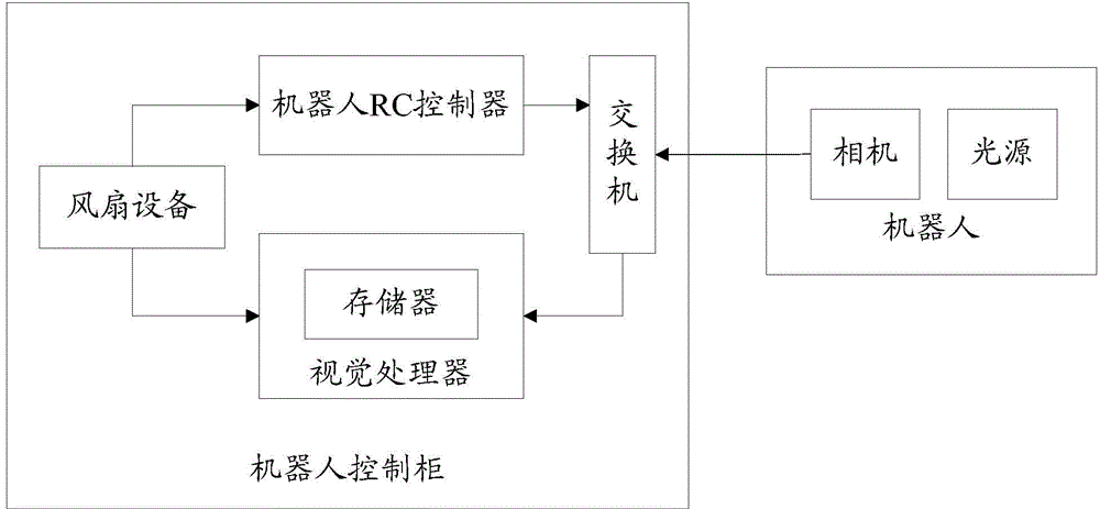
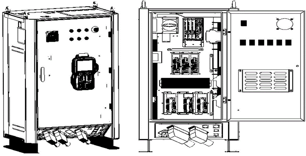
[0032] see figure 1 , is a schematic structural diagram of the hardware of the robot vision system according to the embodiment of the present invention. The hardware of the robot vision system in the embodiment of the present invention includes a camera, a light source, a robot control cabinet, a robot RC controller, a vision processor, and a switch, wherein the camera adopts the "eye-on-hand" or "eye-in-hand" fixed Way. The "eye-on-hand" method means that the camera is fixed on the bracket above the conveyor belt or on the bracket of other equipment. The "eye-in-hand" method means that the came...


PUM


Abstract

The invention belongs to the technical field of robot vision systems, in particular to a robot vision system. The robot vision system comprises a camera, a robot control cabinet, a robot RC control, a vision processor and an interchanger, wherein the robot RC control, the vision processor and the interchanger are all arranged in the robot control cabinet; and the camera and the robot RC control are both connected with the network of the vision processor through the interchanger. According to the robot vision system, the vision processor is integrated in the robot control cabinet, so that the size and weight of the camera are structurally reduced; the application is convenient; the cost of the camera is favorably lowered; a PC 104 board card based on an X86 structure is adopted as a processor by the vision processor, so that the calculation capacity of the processor is higher than that of a processor in a current intelligent camera; furthermore, sufficient space is provided for heat dissipation; and the reliability of the system is more higher.

Description

technical field [0001] The invention belongs to the technical field of robot vision, and in particular relates to a robot vision system. Background technique [0002] The combination of industrial robots and vision is the future development direction. At present, the vision systems used in the field of industrial robots are generally divided into two categories: one is the use of smart cameras, that is, the camera and processor are integrated, and the vision algorithm runs in the processor. , the smart camera is equipped with a host computer software module, through which the algorithm input parameters in the smart camera can be configured accordingly; there is another type that uses ordinary industrial cameras and is equipped with a PC. Ordinary cameras only have cameras and lenses, without The processor, the vision algorithm runs on the PC. [0003] The two types of vision systems have their own advantages and disadvantages: the first type uses smart cameras with relative...

Claims


Application Information

Patent Timeline
IPC IPC(8): B25J19/04
Inventor 邹风山李邦宇董状刘晓帆姜楠李燊
Owner SHENYANG SIASUN ROBOT & AUTOMATION
Learn More