High pressure cylinder shaft seal device for power station steam turbine

A high-pressure cylinder, steam turbine technology, applied in mechanical equipment, engine components, machines/engines, etc., can solve problems such as large shaft seal clearance and loose shaft seals

Pending Publication Date: 2016-05-18
SHANXI GUOFENG COAL POWER CO LTD +1
View PDF7 Cites 2 Cited by
  • Summary
  • Abstract
  • Description
  • Claims
  • Application Information

AI Technical Summary

Problems solved by technology

[0003] The purpose of the present invention is to overcome the deficiencies of the above-mentioned prior art, and propose a shaft seal device for a high-pressure cylinder of a steam turbine in a power station, so as to solve the problem of large shaft seal clearance and loose shaft seal due to the difficulty in controlling the shaft seal clearance of the existing steam turbine high-pressure cylinder shaft seal. question

Method used


Image

  • High pressure cylinder shaft seal device for power station steam turbine
  • High pressure cylinder shaft seal device for power station steam turbine

Examples


Embodiment Construction

[0019] The following will clearly and completely describe the technical solutions in the embodiments of the present invention with reference to the accompanying drawings in the embodiments of the present invention. Obviously, the described embodiments are only some, not all, embodiments of the present invention. Based on the embodiments of the present invention, all other embodiments obtained by persons of ordinary skill in the art without making creative efforts belong to the protection scope of the present invention.

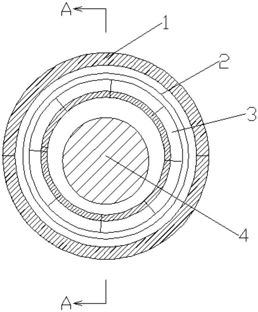
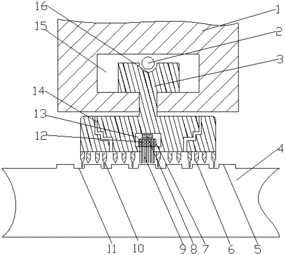
[0020] Such as figure 1 with 2 Shown is a schematic structural view of the high-pressure cylinder shaft seal device of the steam turbine in the power station in the embodiment.

[0021]A shaft seal device for a high-pressure cylinder of a steam turbine in a power station in an illustrative embodiment. The shaft seal sleeve 1 of the high-pressure cylinder is composed of upper and lower parts. The inner surface of the shaft seal sleeve 1 of the high-pressure cy...


PUM


Abstract

A high pressure cylinder shaft seal device for a power station steam turbine aims to solve the problem of the big shaft seal gap of a high pressure cylinder of the power station steam turbine. The high pressure cylinder shaft seal device comprises a high pressure cylinder shaft seal cover, a round spring, arc-shaped shaft seal blocks, a rotating shaft, bosses, low sealing teeth, brush sealing bodies, a leaf spring, high sealing teeth, grooves, an annular brush sealing body cavity and an annular shaft seal ring cavity. The annular shaft seal ring cavity is formed in the inner side face of the high pressure cylinder shaft seal cover; the sections of the arc-shaped shaft seal blocks are in an I shape; the multiple arc-shaped shaft seal blocks constitute a shaft seal ring; the outer ends of the arc-shaped shaft seal blocks are arranged in the shaft seal ring annular cavity; a semicircular groove channel is formed in the outer edges of the arc-shaped shaft seal blocks in the circumferential direction; the lower half part of the round spring is fastened in the semicircular groove, and the upper half part of the round spring is exposed between the shaft seal ring and the annular shaft seal ring cavity; the annular brush sealing body cavity is formed in the center of the inner side faces of the arc-shaped shaft seal blocks; the multiple brush sealing bodies constitute a brush sealing ring; and the outer side end of the brush sealing ring is arranged in the brush sealing body annular cavity in a sleeved mode.

Description

technical field [0001] The invention relates to the technical field of steam turbine shaft seals in power stations, in particular to a shaft seal device for high-pressure cylinders of steam turbines in power stations. Background technique [0002] The seal between the rotating shaft and the cylinder of the power station steam turbine, that is, the shaft seal, mainly includes fir tree type shaft seal, comb type shaft seal, brush type shaft seal, etc. At present, the high pressure cylinder of the power station steam turbine generally adopts a single comb type shaft seal. The hardness of the material of the shaft seal body is greater than that of the rotating shaft of the high-pressure cylinder, and the thermal expansion and contraction coefficients are different. In order to obtain a better sealing effect, the gap between the comb-shaped shaft seal body and the high-pressure cylinder shaft is generally designed to be relatively small. When the steam turbine rotor exceeds the c...

Claims


Application Information

Patent Timeline
Patent Type & Authority Applications(China)
IPC IPC(8): F01D11/00
CPCF01D11/003F05D2240/56
Inventor 柳成亮李东雄郝海俊徐鸿恩姜英栋
Owner SHANXI GUOFENG COAL POWER CO LTD
Why Eureka
Try Eureka