

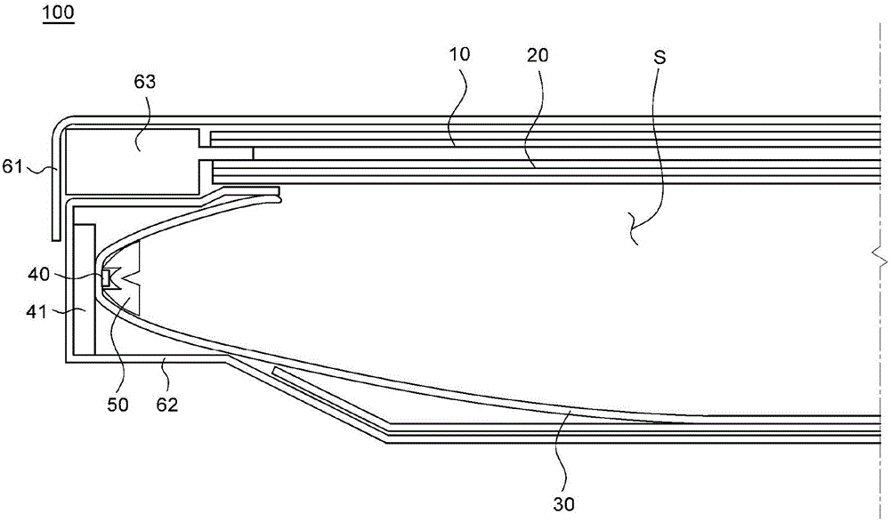
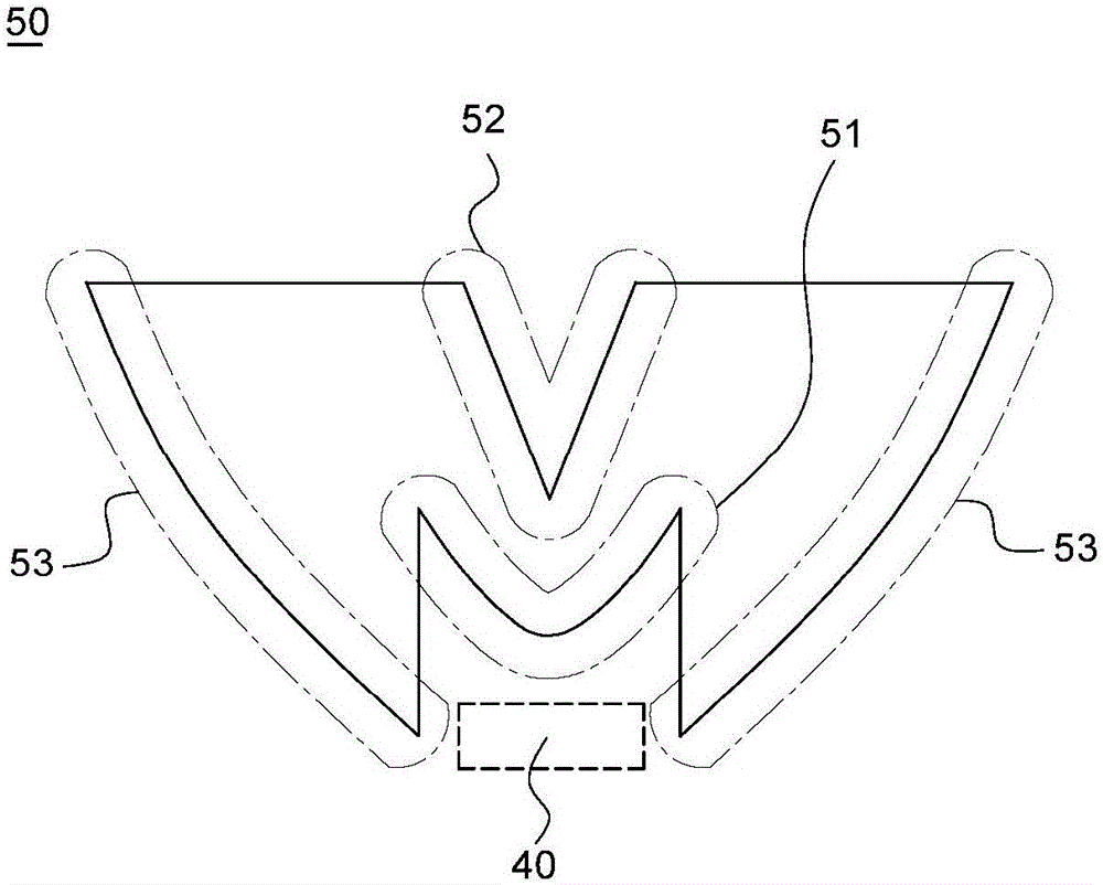
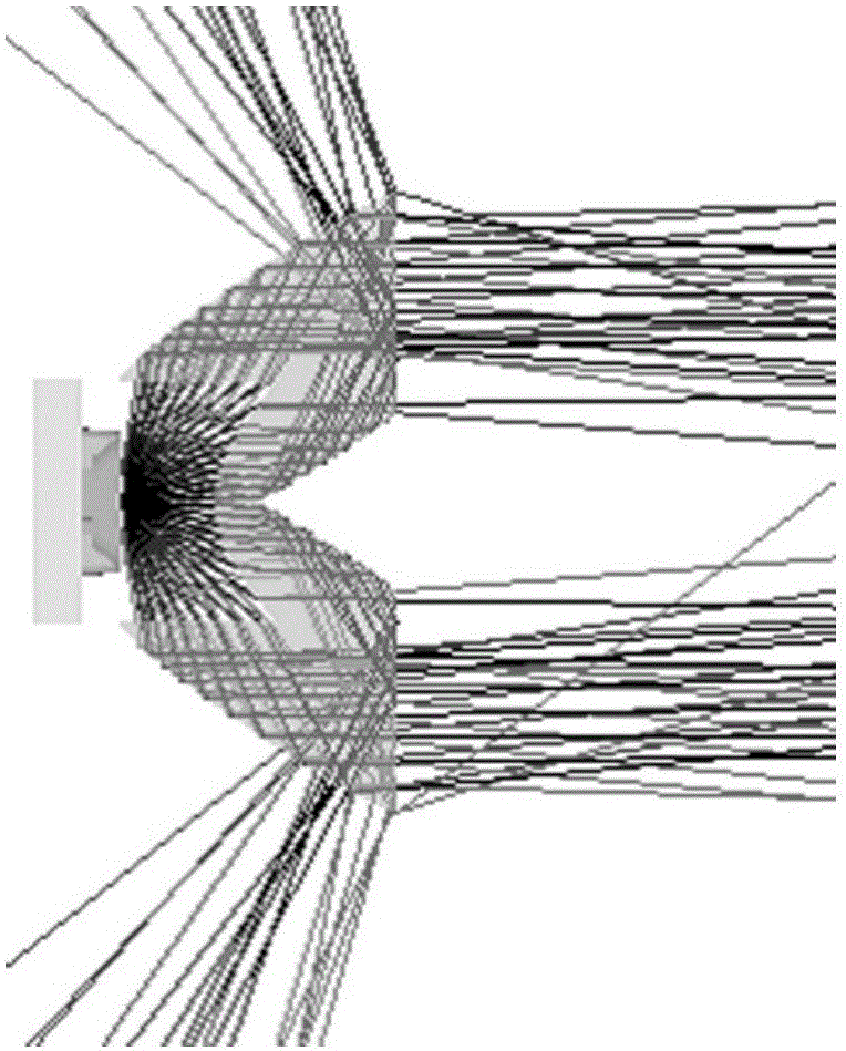
Lens for edge light type display device and display device having the same
A side-light type, light guide plate technology, applied in the directions of lenses, light guides, optics, etc., can solve the problems of insufficient diffusion distance of the light source 40, difficulty in achieving thinning of the display device, and limited size of the display device, and reduce the thickness of the frame. , Improve the effect of light concentration and hot spots
- Summary
- Abstract
- Description
- Claims
- Application Information
AI Technical Summary
Problems solved by technology
Method used
Image

Examples
Embodiment Construction
[0029] Advantages and features of the present invention, and means for achieving them will be clearly understood by referring to the accompanying drawings and embodiments described in detail later. However, the present invention is not limited to the embodiments disclosed below, but can be realized in various forms. The present embodiment is provided only to fully disclose the present invention and to fully inform the scope of the invention to those having ordinary knowledge in the art, and the present invention should be defined by the scope of the claims.
[0030] The so-called element (elements) or layer "above (on)" of another element or layer includes the situation that the element (elements) or layer is directly arranged on the other element or layer and other layers or other elements are arranged in between. The condition of the component.
[0031] Although the expressions first, second, etc. are used to describe various components, it goes without saying that these co...
PUM
 Abstract
Description
Claims
Application Information