
Common Mode Choke

A technology of common mode choke coils and coils, which is applied in the directions of transformer/inductor coil/winding/connection, inductors, printed inductors, etc., which can solve the obstacles to the miniaturization of common mode choke coils and the freedom of coil shape design problems such as lowering and lowering of withstand voltage reliability, etc., to achieve the effects of easy adjustment, improved design freedom, and reduced drop in withstand voltage reliability

Active Publication Date: 2018-05-18
MURATA MFG CO LTD
View PDF6 Cites 0 Cited by
  • Summary
  • Abstract
  • Description
  • Claims
  • Application Information

AI Technical Summary

Problems solved by technology

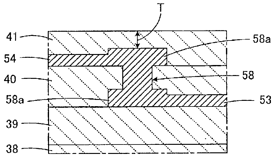
[0025] As mentioned above, the problem of reduction in withstand voltage reliability due to the diffusion of the conductor material and the reduction in the thickness of the insulating layer for the outer peripheral side via-hole conductor is that the degree of freedom in the design of the coil shape of the common mode choke coil is reduced. s reason
In addition, if the thickness of the insulating layer is increased in order to improve the reliability of the withstand voltage, it will hinder the miniaturization of the common mode choke coil.

Method used


Image

  • Common Mode Choke
  • Common Mode Choke
  • Common Mode Choke

Examples


Embodiment Construction

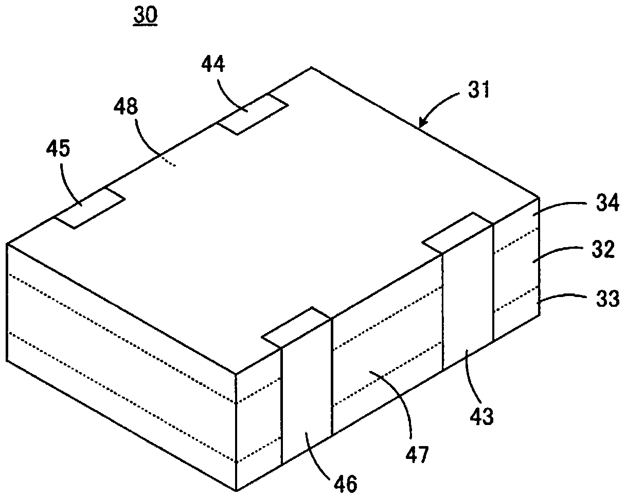
[0047] refer to figure 1 , the common mode choke coil 30 includes a laminated body 31 as a component main body. The laminated body 31 has a structure in which the low magnetic permeability portion 32 is sandwiched between the two magnetic body portions 33 and 34 . The magnetic body portions 33 and 34 are made of, for example, Ni—Cu—Zn-based ferrite, Mn—Zn-based ferrite, hexagonal-based ferrite, or the like. On the other hand, as the material of the low magnetic permeability portion 32, for example, non-magnetic materials such as glass ceramics with a magnetic permeability of almost 1, Ni-Cu-Zn-based ferrite with a magnetic permeability of about 1 to 10, non-magnetic materials, etc., can be used. Magnetic ferrite, etc. In addition, resins such as polyimide can also be used as the material of the low magnetic permeability portion 32 .

[0048] First to fourth external terminal electrodes 43 to 46 are provided on the outer surface of the laminated body 31 . More specifically...


PUM


Abstract

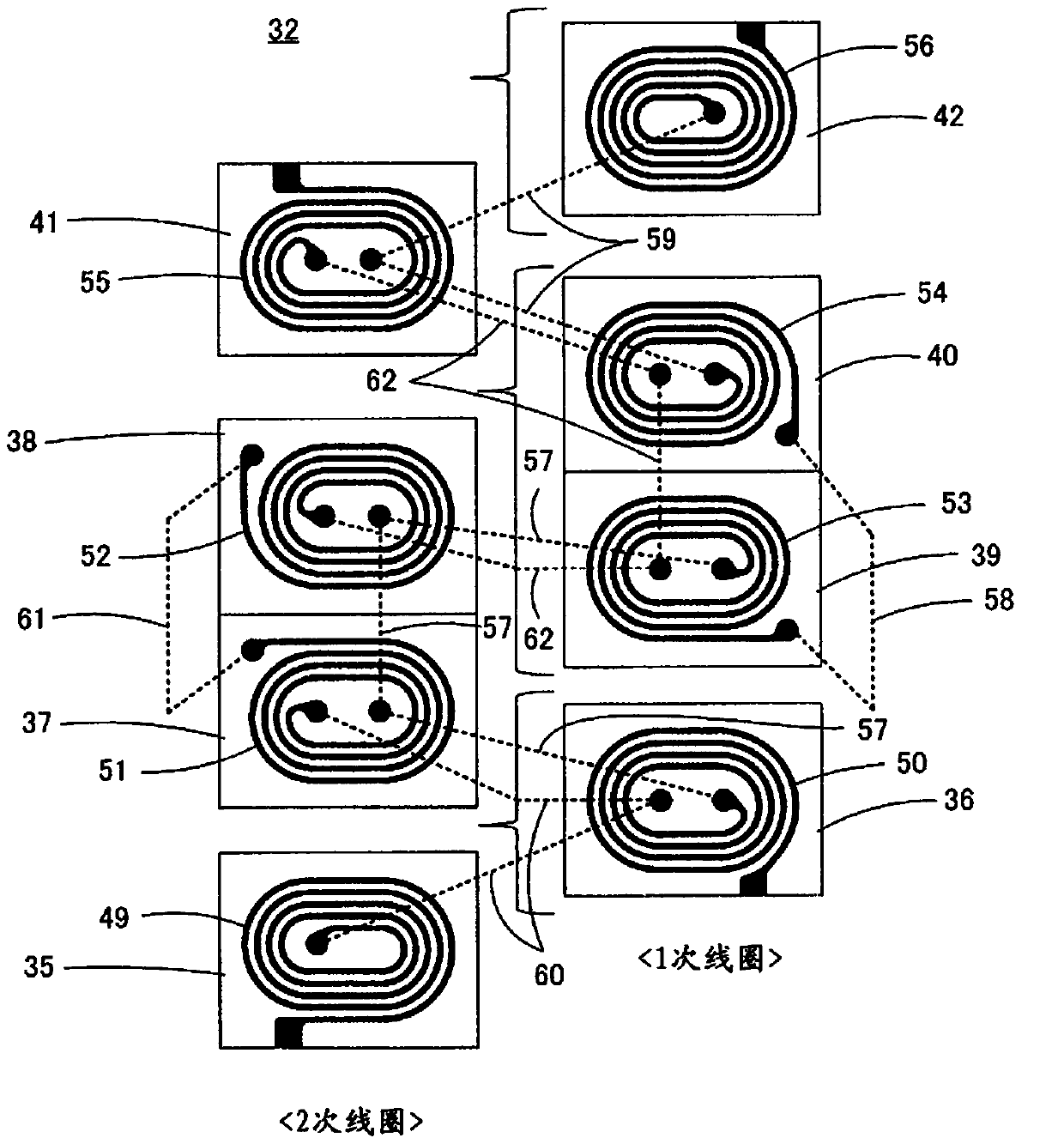
A common mode choke coil includes a laminated-type coil that has high breakdown voltage reliability. Coil conductors and a coil conductor for a secondary coil are laminated so as to be respectively interposed between, coil conductors for a primary coil, two coil conductors connected to each other by an inner circumferential side via hole conductor and two coil conductors connected by an inner circumferential side via hole conductor. Meanwhile, in the primary coil, an outer circumferential side via hole conductor is provided so as to pass through only one insulation layer, and accordingly, a length of the outer circumferential side via hole conductor in an axis line direction thereof is reduced. As a result, an amount of conductive material used for the outer circumferential side via hole conductor that diffuses during firing can be reduced, and a drop in a thickness of the insulation layers can be suppressed.

Description

technical field [0001] The present invention relates to a common mode choke coil, and more particularly to a common mode choke coil including a laminated coil. Background technique [0002] A common mode choke coil including a laminated coil includes a laminated body having a laminated structure including a plurality of laminated insulating layers, and a coil is provided inside the laminated body. The coil includes a plurality of helical coil conductors. The plurality of coil conductors respectively have an inner peripheral end located near a relatively central portion of the insulating layer and an outer peripheral end located near a relatively outer periphery, the inner peripheral end is connected to an inner peripheral via-hole conductor, and the outer peripheral end The outer peripheral side via-hole conductor is connected. In addition, in order to create portions of the coil in which the winding directions are opposite to each other, the inner peripheral end portions ...

Claims


Application Information

Patent Timeline
Patent Type & Authority Patents(China)
IPC IPC(8): H01F27/28H01F27/29
CPCH01F27/292H01F17/0013H01F2017/002H01F2017/0093
Inventor 乾真规
Owner MURATA MFG CO LTD
Learn More