
Fuel cell separator, fuel cell and fuel cell battery

A technology for fuel cells and separators, which is applied in the directions of fuel cells, electrical components, circuits, etc., can solve the problems of reduced sealing performance and inability to suppress deformation of manifold beams.

Active Publication Date: 2016-05-18
TOYOTA JIDOSHA KK
View PDF6 Cites 8 Cited by
  • Summary
  • Abstract
  • Description
  • Claims
  • Application Information

AI Technical Summary

Problems solved by technology

Regarding this point, when the technique described in Patent Document 1 is adopted, there is a possibility that the region between the power generation unit and the manifold can be reinforced, but the deformation of the beam portion of the manifold cannot be suppressed, and the problem of a decrease in sealing performance remains.

Method used


Image

  • Fuel cell separator, fuel cell and fuel cell battery
  • Fuel cell separator, fuel cell and fuel cell battery
  • Fuel cell separator, fuel cell and fuel cell battery

Examples


Embodiment Construction

[0027] Hereinafter, embodiments of the present invention will be described with reference to the drawings. It should be noted that, unless otherwise specified, positional relationships such as up, down, left, and right in the drawings are based on the positional relationships shown in the drawings. In addition, the dimensional ratios in the drawings are not limited to the illustrated ratios. In addition, the following embodiments are examples for explaining the present invention, and the present invention is not limited to the embodiments. Furthermore, the present invention can be modified in various ways as long as it does not deviate from the gist.

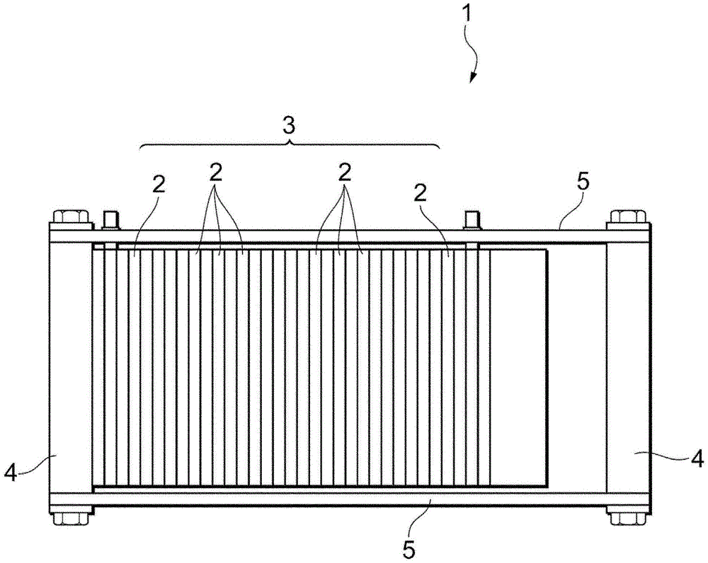
[0028] First, use figure 1 , the structure of the fuel cell 1 according to the embodiment of the present invention will be described.

[0029] The fuel cell 1 of the present embodiment includes a unit cell stack 3 formed by sequentially stacking a plurality of fuel cell units 2 . Both ends of the cell stack 3 are clamped by ...


PUM


Abstract

The invention relates to a fuel cell separator, a fuel cell and a fuel cell battery. It is an object of the present invention to prevent deterioration in sealing performance by suppressing the deformation of manifold portions of a fuel cell separator. A fuel cell separator 10 includes a power generation section 10B provided in a central region on a surface of the separator formed into a plate, a plurality of manifolds 11A, 11B, 12A, and 12B provided in a region closer to the outer periphery than the power generation section 10B, and a reinforcing portion 14A provided so as to extend from a manifold beam portion 15 formed between the plurality of manifolds 11A, 11B, 12A, and 12B to a gap region 13 formed between the power generation section 10B and the manifolds 11A, 11B, 12A, and 12B.

Description

technical field [0001] The present invention relates to a fuel cell separator, a fuel cell and a fuel cell. Background technique [0002] Conventionally, fuel cells including a membrane electrode assembly (MEA: Membrane-Electrode Assembly) formed by providing catalyst layers for electrodes on both surfaces of an electrolyte membrane and separators sandwiching the MEA have been proposed and put into practical use. In the fuel cell system including the fuel cell described above, fuel gas is supplied to one electrode (anode electrode) of the MEA constituting the fuel cell and an oxidizing gas is supplied to the other electrode (cathode electrode) to generate an electrochemical reaction, thereby proceeding. generate electricity. Currently, a technique is employed in which a plurality of single fuel cells having a single MEA are stacked to form a stack (cell stack) to generate large electric power. [0003] The separator constituting the fuel cell is a plate-shaped member havin...

Claims


Application Information

Patent Timeline
Patent Type & Authority Applications(China)
IPC IPC(8): H01M8/0252H01M8/0258
CPCH01M8/0252H01M8/0258H01M8/0247H01M8/0267H01M2008/1095Y02E60/50
Inventor 冈部裕树绀野周重
Owner TOYOTA JIDOSHA KK
Learn More