Bur removing device of plastic sleeve

A plastic sleeve and deburring technology, which is applied in the field of stamping devices, can solve the problems of low pass rate, plastic sleeve cannot be sleeved on the outside of the terminal, and low production efficiency, so as to achieve extended service life and convenient and quick movement. Effect

Active Publication Date: 2016-05-18
乐清市超导电器联接有限公司
View PDF8 Cites 6 Cited by
  • Summary
  • Abstract
  • Description
  • Claims
  • Application Information

AI Technical Summary

Problems solved by technology

[0003] Since the stamping process adopts the method of cold stamping, the inner wall of the plastic sleeve after stamping will have some burrs that are inevitably generated during the stamping process, which makes the inner wall of the plastic sleeve uneven and smooth, so that in the next process plastic There are many unqualified products in the assembly of sleeves and terminals. Unqualified plastic sleeves with burrs cannot be sleeved on the outside of the terminals, resulting in low production efficiency, low pass rate, low factory output, and low factory value, resulting in unnecessary waste

Method used


Image

  • Bur removing device of plastic sleeve
  • Bur removing device of plastic sleeve
  • Bur removing device of plastic sleeve

Examples


Embodiment Construction

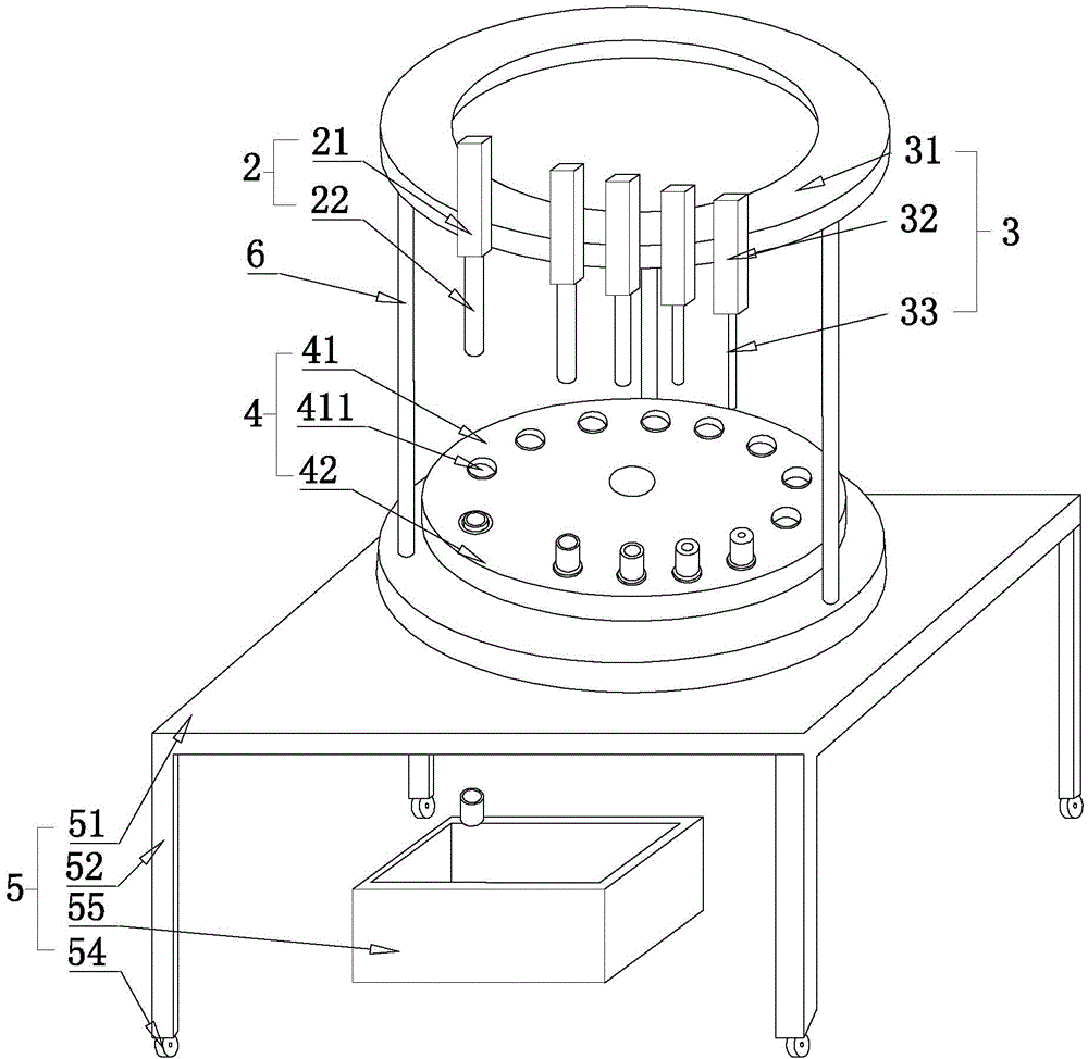
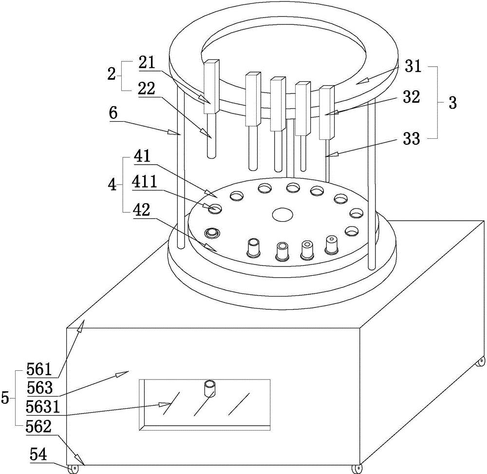
[0029] refer to Figure 1 to Figure 5 The embodiment of the plastic sleeve deburring device of the present invention will be further described.

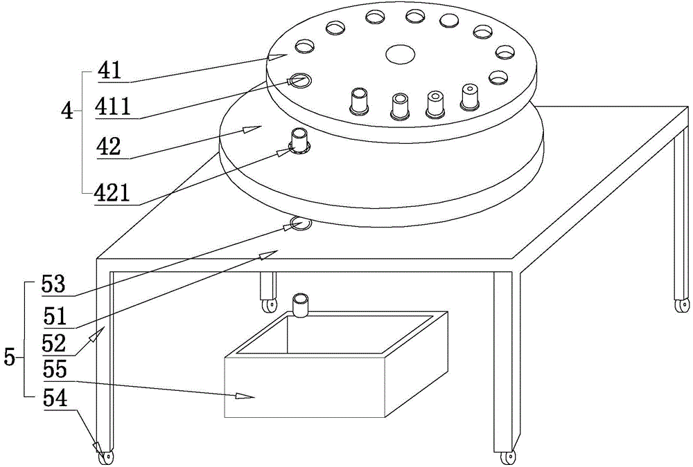
[0030] A deburring device for a plastic sleeve 1, comprising a rotating mechanism 4 for placing the plastic sleeve 1, a stamping mechanism 3 arranged above the rotating mechanism 4, and a deburring mechanism 2, the rotating mechanism 4 includes a fixed plate 42 and a peripheral To the rotating disc 41, the fixed disc 42 is arranged on the opposite side of the rotating disc 41 relative to the stamping mechanism 3, and the upper circumference of the rotating disc 41 is distributed with fixing through holes 42 for fixing the plastic sleeve 1;

[0031] The stamping mechanism 3 includes an annular base 31, a number of stamping rods 33 for conflicting with the inner wall of the plastic sleeve 1, a stamping drive device 32 fixed on the annular base 31 for driving the stamping rods 33 to sit up and down, and for connecting The connecting co...


PUM


Abstract

Disclosed in the invention is a bur removing device of a plastic sleeve. The device comprises a rotation mechanism, a punching mechanism and a bur removing mechanism. The rotation mechanism includes a fixed plate and a rotation plate; the fixed plate is arranged at the opposite side, relative to the punching mechanism, of the rotation plate; and fixed through holes for fixing a plastic sleeve are distributed in the rotation plate at the peripheral direction. The punching mechanism consists of an annular pedestal, punching rods, a punching drive unit, and connecting posts; the punching rods with the external diameters increasing in an ascending order are distributed on the annular pedestal successively along the periphery; the positive projection of the punching rods on the rotation plate are superposed with the axis of the plastic sleeve; and the punching rods are fixedly connected to the output terminal of the punching drive unit. The bur removing mechanism includes an independent drive unit and a bur removing rod fixedly connected to the output terminal of the independent drive unit, wherein the external diameter of the bur removing rod is identical with the external diameter of the adjacent punching rod. The device has the following advantages: burs formed at the inner wall of the plastic sleeve of the wiring terminal can be removed; the production efficiency and the yield are improved; the output amount and the output value are increased; and unnecessary wasting is reduced.

Description

technical field [0001] The invention relates to a punching device in production equipment, in particular to a device for punching and deburring plastic sleeves of terminal blocks. Background technique [0002] The traditional device for stamping the plastic sleeve on the terminal includes a punching mechanism and a rotating mechanism for placing the plastic sleeve. The rotating mechanism is distributed with fixed bases for fixing the plastic sleeve. The punching mechanism includes a ring base and a circumferential distribution. The stamping rods arranged clockwise on the annular base and arranged clockwise in order of thickness from small to large, the stamping rods are aligned with the axis of the plastic sleeve. [0003] Since the stamping process adopts the method of cold stamping, the inner wall of the plastic sleeve after stamping will have some burrs that are inevitably generated during the stamping process, which makes the inner wall of the plastic sleeve uneven and s...

Claims


Application Information

Patent Timeline
IPC IPC(8): H01R43/18
Inventor 叶志超
Owner 乐清市超导电器联接有限公司
Why Eureka
Try Eureka