Permanent magnet electromagnetic composite disc type eddy current braking device

An electromagnetic compound, eddy current braking technology, applied in the direction of permanent magnet clutch/brake, electromechanical device, electric brake/clutch, etc. Improved energy transfer efficiency, reduced maintenance effort, and effects in terms of braking force regulation

Active Publication Date: 2016-05-18
INST OF ELECTRICAL ENG CHINESE ACAD OF SCI
View PDF8 Cites 23 Cited by
  • Summary
  • Abstract
  • Description
  • Claims
  • Application Information

AI Technical Summary

Problems solved by technology

However, the current problem is that the output braking torque of the permanent magnet eddy current brake device cannot be adjusted, which limits the applicability of the permanent magnet eddy current brake device
However, the output torque of this adjustable-speed disc-type magnetic coupling is limited, and the permanent magnet disc needs to be in a moving state for a long time, which has high requirements for the installation reliability of the mechanical device
[0007] The Chinese patent of CN102270911A discloses a magnetic coupler in which the permanent magnet in the magnetic rotor is fan-shaped, the braking source is a permanent magnet, and the magnetic force is not adjustable
The retarder achieves the purpose of decelerating the vehicle when the speed is too fast, but if the electromagnet control fails, the braking effect will be completely lost
[0009] Summing up the above prior art, it can be known that the amount of permanent magnet used for permanent magnet linear braking is large. For example, when the permanent magnet used for braking is laid on the track, the permanent magnet utilization rate is very low, the volume is large, and the quality is heavy, which easily deforms the track. , leading to changes in parameters such as clearances that affect braking performance
The existing speed-adjustable magnetic coupling of the rotating structure adopts a disc-shaped structure, which is compact in structure and reduces the space occupied by the braking device, but the braking power is not adjustable
The permanent magnet electromagnetic compound brake can adjust the output power, but the output torque is limited

Method used


Image

  • Permanent magnet electromagnetic composite disc type eddy current braking device
  • Permanent magnet electromagnetic composite disc type eddy current braking device
  • Permanent magnet electromagnetic composite disc type eddy current braking device

Examples


Embodiment Construction

[0044] The present invention will be further described below in conjunction with the accompanying drawings and specific embodiments.

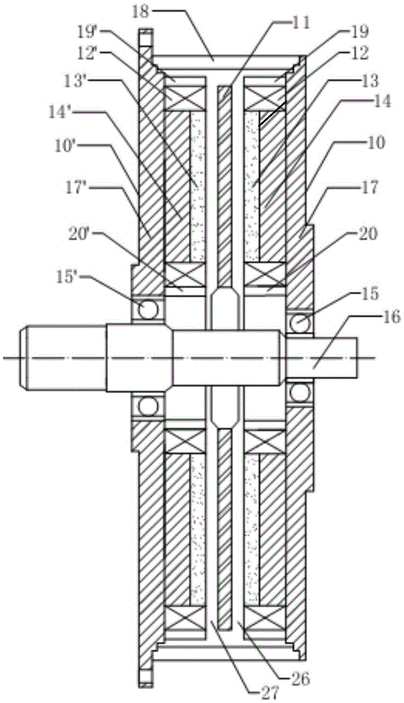
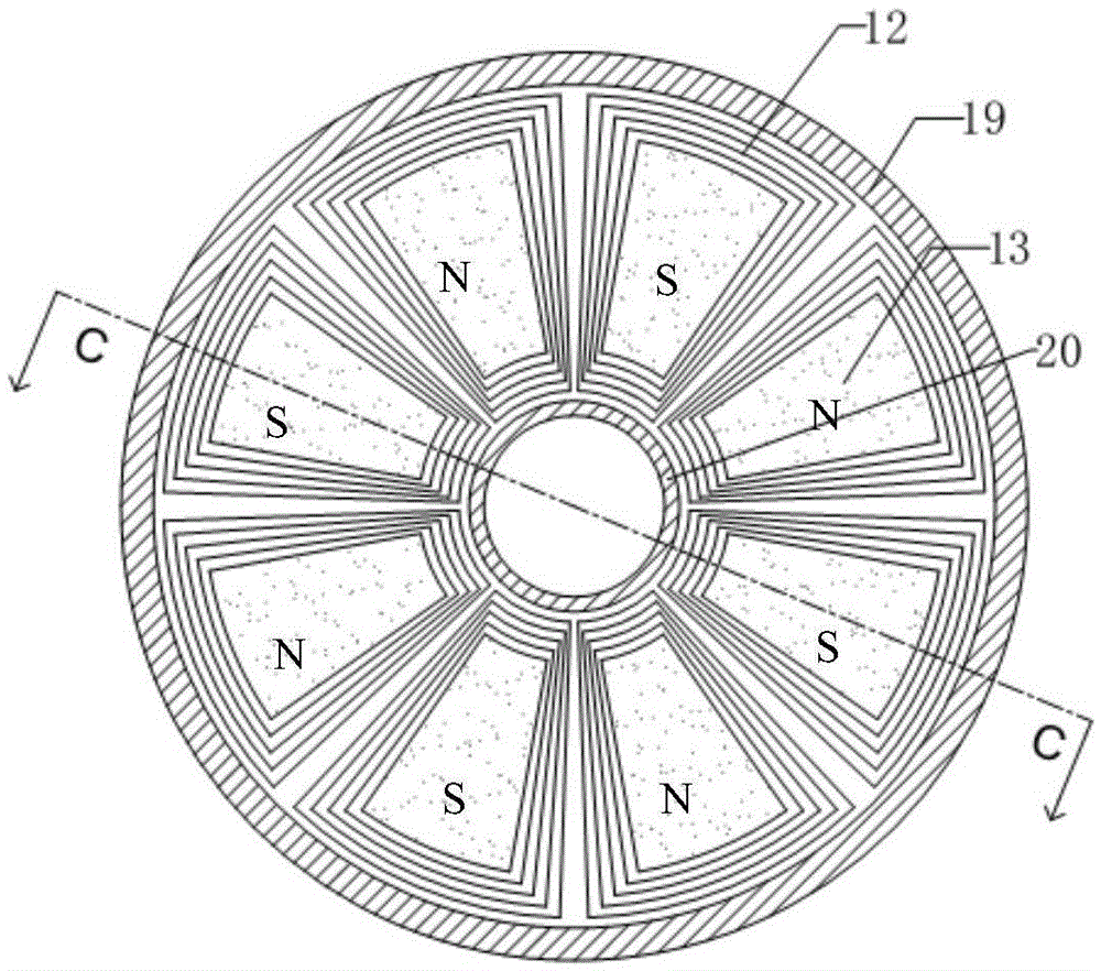
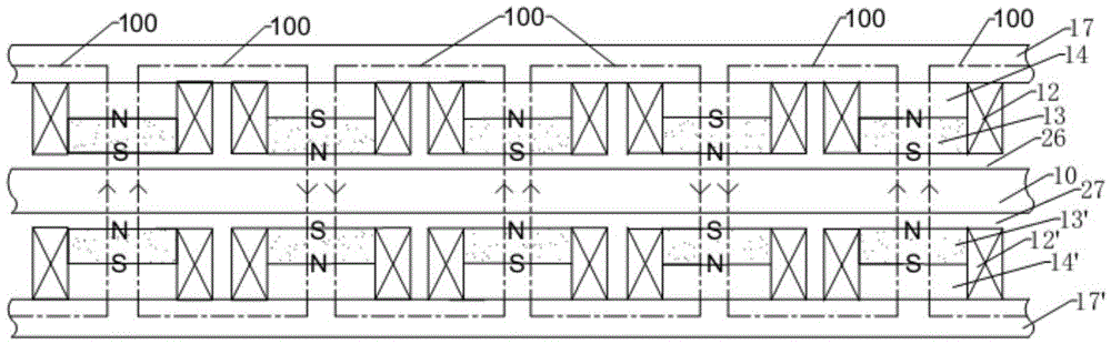
[0045] The permanent magnet electromagnetic composite disk type eddy current braking device of the present invention comprises two magnet disks 10, 10 ', one metal disk 11 and a transmission shaft. The two magnet discs 10, 10' are fixed on the stationary equipment in parallel; the body structures of the two magnet discs 10, 10' are the same, and they are placed symmetrically on both sides of the metal disc. The metal disc 11 is coaxially installed between the two magnet discs 10, 10', parallel with the two magnet discs 10, 10', and fixed on the transmission shaft. Transmission shaft is supported on two sides magnet disk 10,10' by bearing 15,15'. Each magnet disk is evenly spaced along the circumference with m compound magnetic poles compounded by permanent magnets and electromagnets, where m is an even number, and the m compound magnetic poles...


PUM


Abstract

Provided is a permanent magnet electromagnetic composite disc type eddy current braking device. The device comprises two magnet discs, a metal disc, and a transmission shaft, the two magnet discs are fixed on static equipment in parallel, the metal disc is fixed on the transmission shaft and arranged between the two magnet discs in parallel, the metal disc and the two magnet discs are also coaxially installed, the transmission shaft is supported on the two magnet discs via bearings, each magnet disc is provided with m composite magnetic poles formed by permanent magnets and electromagnets along the circumference (m is an even number), the m composite magnetic poles on the two magnet discs are opposite in pairs in the axis direction, and the magnetic field at the position of the metal disc between the two magnet discs is changed via the adjustment of the current and direction of electromagnet coils. When the metal disc and the magnet discs generate relative movement, eddy current is generated in the metal disc, interaction is generated, and rapid braking between the metal disc and the transmission shaft and moving bodies connected with the metal disc is realized. The braking device is applicable to rapid braking of high-speed moving bodies.

Description

technical field [0001] The invention relates to a permanent magnet electromagnetic composite disc eddy current braking device for braking a high-speed moving body. Background technique [0002] The braking devices of high-speed moving bodies such as motor vehicles and motor acceleration mechanisms often use brake pads to contact the brake disc to generate friction, thereby generating braking, that is, mechanical friction braking. However, in the case of high-speed movement, if mechanical friction braking is used, it will cause problems such as mechanical wear of wheels or brake discs and other components, noise friction and thermal stress, and the maintenance workload will also increase greatly. At present, the problem of friction braking is solved The measures mainly include improving the contact surface material and contact mode, but they cannot completely overcome the defects caused by mechanical friction braking. [0003] Magnetic eddy current braking can achieve brakin...

Claims


Application Information

Patent Timeline
Patent Type & Authority Applications(China)
IPC IPC(8): H02K49/04H02K49/10
CPCH02K49/046H02K49/10
Inventor 史黎明王培龙董桂丽杜玉梅李耀华
Owner INST OF ELECTRICAL ENG CHINESE ACAD OF SCI
Why Eureka
Try Eureka