Channel detection control method, correlative equipment, and system

A channel detection and control method technology, applied in the field of communication, can solve problems such as unfavorable efficiency and increased power consumption of transmission nodes.

Inactive Publication Date: 2016-05-18
SHENZHEN GIONEE COMM EQUIP
View PDF5 Cites 29 Cited by
  • Summary
  • Abstract
  • Description
  • Claims
  • Application Information

AI Technical Summary

Problems solved by technology

More LBT detection is detrimental to the efficiency of the system. In addition, t

Method used


Image

  • Channel detection control method, correlative equipment, and system
  • Channel detection control method, correlative equipment, and system
  • Channel detection control method, correlative equipment, and system

Examples


Embodiment Construction

[0037] The following will clearly and completely describe the technical solutions in the embodiments of the present invention with reference to the accompanying drawings in the embodiments of the present invention. Obviously, the described embodiments are some of the embodiments of the present invention, but not all of them. Based on the embodiments of the present invention, all other embodiments obtained by persons of ordinary skill in the art without making creative efforts belong to the protection scope of the present invention.

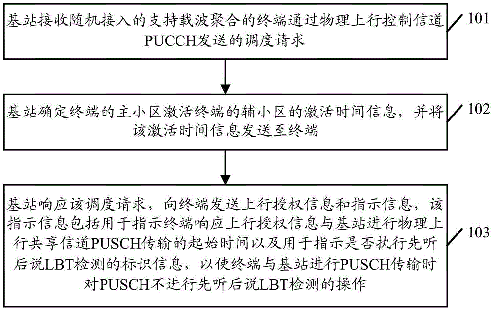
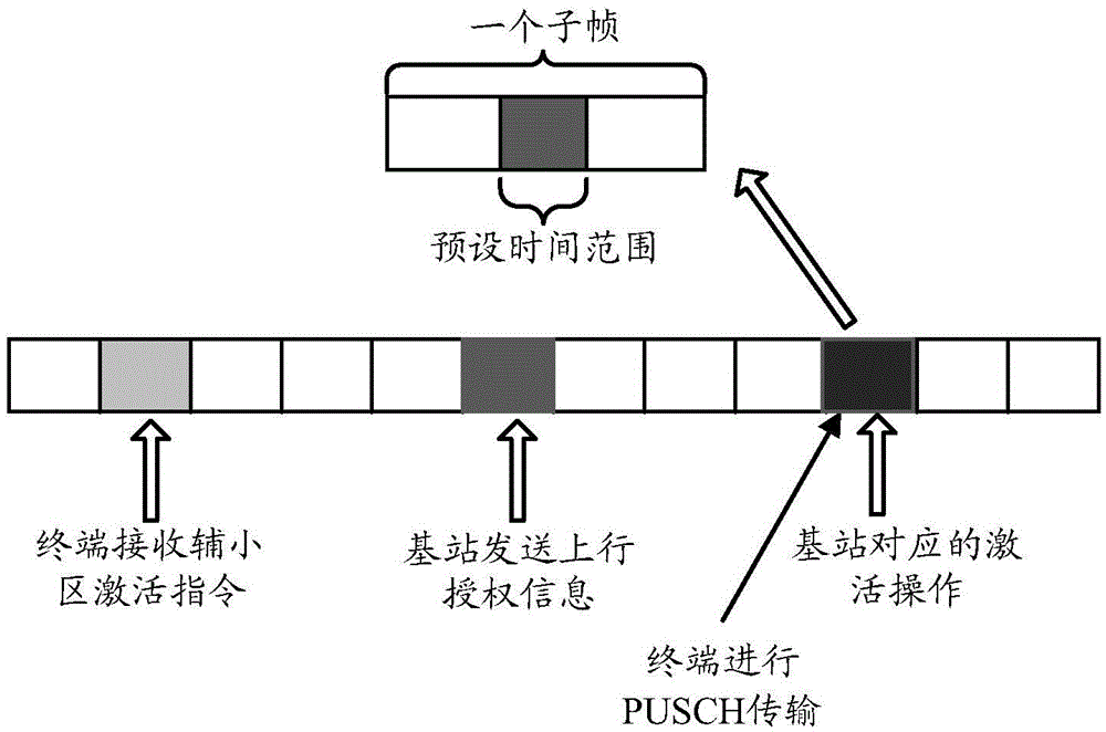
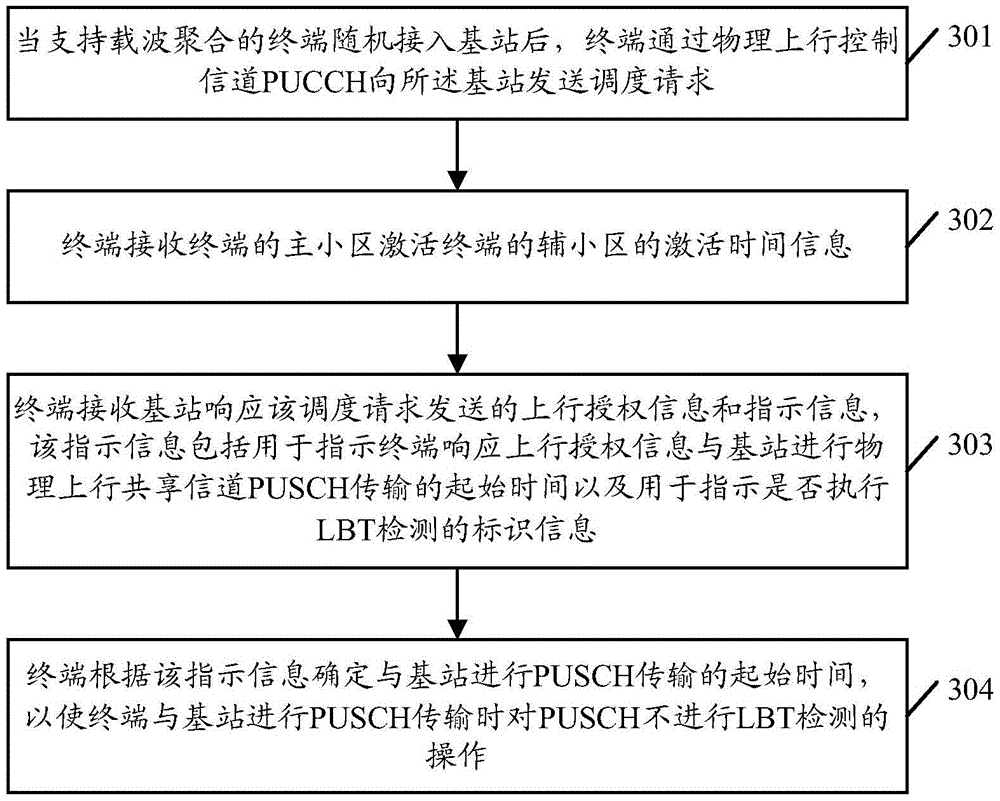
[0038] Embodiments of the present invention provide a channel detection control method and related equipment and system, which can control the start time of PUSCH transmission between the terminal and the base station, so that the interval between the activation time of the secondary cell and the start time of the PUSCH transmission of the terminal Within the preset time range, the terminal does not need to perform LBT detection on the PUSCH channe...


PUM


Abstract

The embodiment of the invention provides a channel detection control method, correlative equipment, and system. The channel detection control method comprises a step that a base station receives a scheduling request transmitted by a randomly-accessed terminal supporting carrier aggregation via a physical uplink control channel (PUCCH), acquires the activation time information that the main cell of the terminal activates the auxiliary cell of the terminal, and transmits uplink authorization information and indication information to the terminal in response to the scheduling request, wherein the indication information is used for indicating the initial time when the terminal performs physical uplink shared channel (PUSCH) transmission with the base station in response to the physical uplink control channel in order that listen before talk (LBT) detection is not carried out on the PUSCH when the terminal and the base station performs PUSCH transmission. The channel detection control method may reduce the number of LBT detection times and decreases the power consumption of the terminal.

Description

technical field [0001] The present invention relates to the field of communication technologies, in particular to a channel detection control method and related equipment and systems. Background technique [0002] Wireless communication networks are widely deployed to provide various communication services such as voice, video, packet data, messaging, and broadcasting. These wireless networks may be multiple-access networks capable of supporting multiple users by sharing available network resources. Examples of such multiple access networks include Code Division Multiple Access (CDMA) networks, Time Division Multiple Access (TDMA) networks, Frequency Division Multiple Access (FDMA) networks, Orthogonal Frequency Division Multiple Access (OFDMA) ) network, single-carrier frequency-division multiple access (Single-carrier Frequency-Division Multiple Access, SC-FDMA) network. [0003] A wireless communication network may include a number of base stations (eg, eNodeBs) that ca...

Claims


Application Information

Patent Timeline
IPC IPC(8): H04W16/14H04W72/04H04W74/08
CPCH04W16/14H04W72/0453H04W74/0808H04W74/0833Y02D30/70
Inventor 乔梁
Owner SHENZHEN GIONEE COMM EQUIP
Why Eureka
Try Eureka